
Feeding and conveying device of soap packaging machine

A conveying device and packaging machine technology, applied in packaging, cooling soap, forming soap, etc., can solve the problems that the conveyor belt is not easy to separate, the quality of packaging soap is uneven, and achieve the effect of convenient packaging

Inactive Publication Date: 2020-03-24
安徽华谊日新科技有限公司
View PDF0 Cites 1 Cited by
  • Summary
  • Abstract
  • Description
  • Claims
  • Application Information

AI Technical Summary

Problems solved by technology

[0003] However, in the prior art, soaps inevitably have size differences when they are cut, and it is not easy to separate them separately when they are transported on the conveyor belt, and the quality of packaged soaps varies.

Method used


Image

  • Feeding and conveying device of soap packaging machine
  • Feeding and conveying device of soap packaging machine
  • Feeding and conveying device of soap packaging machine

Examples


Embodiment 1

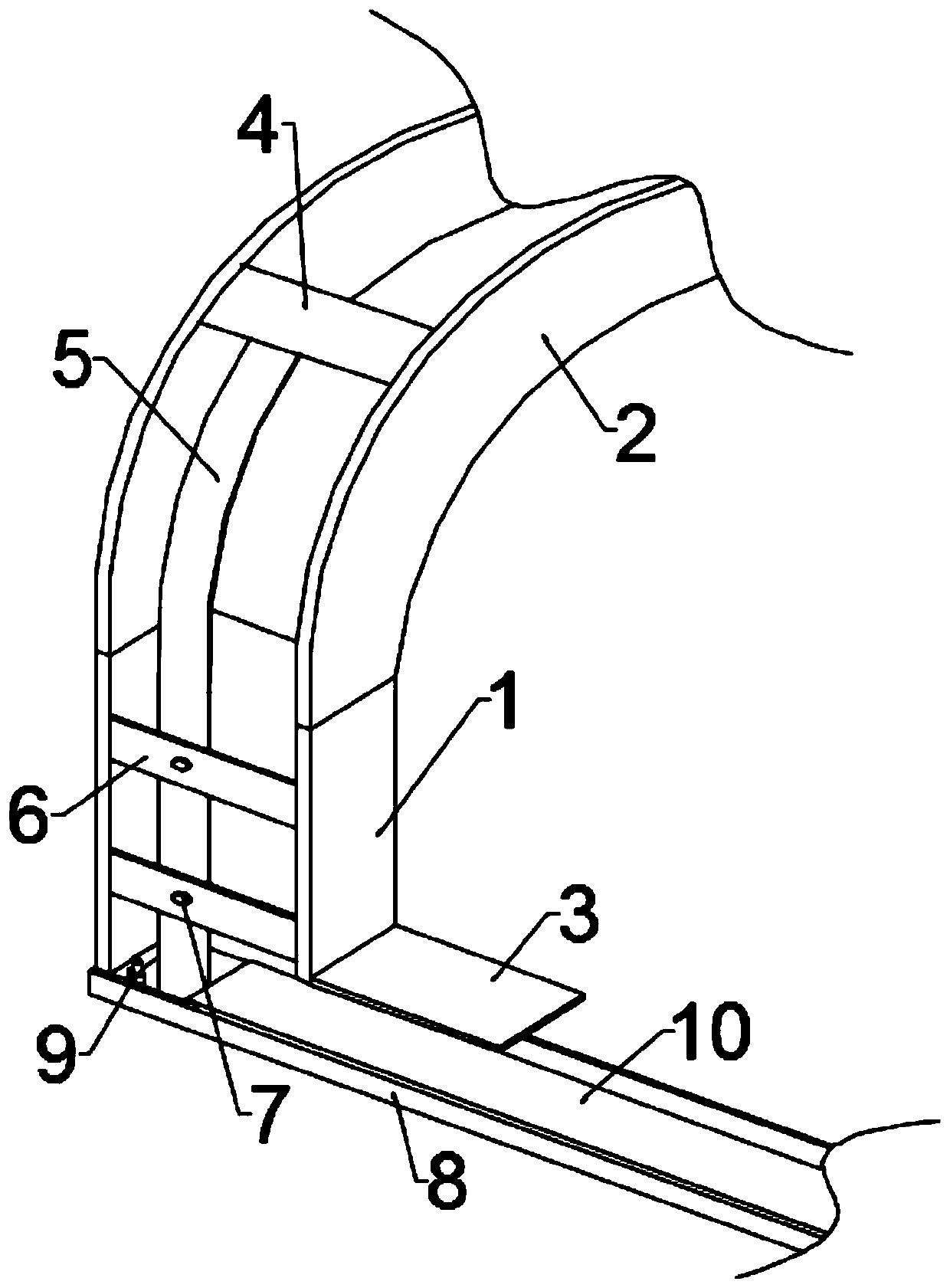
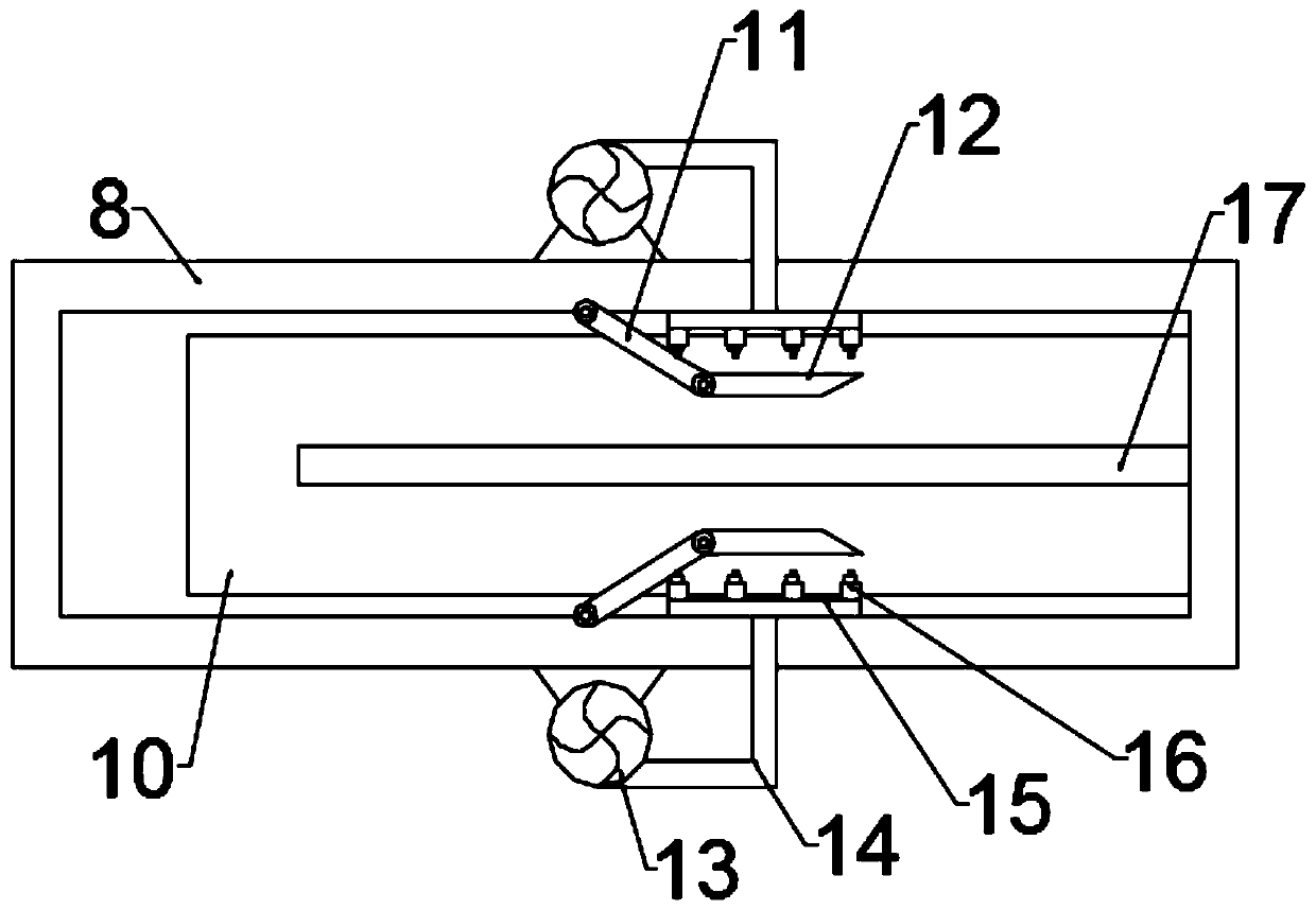
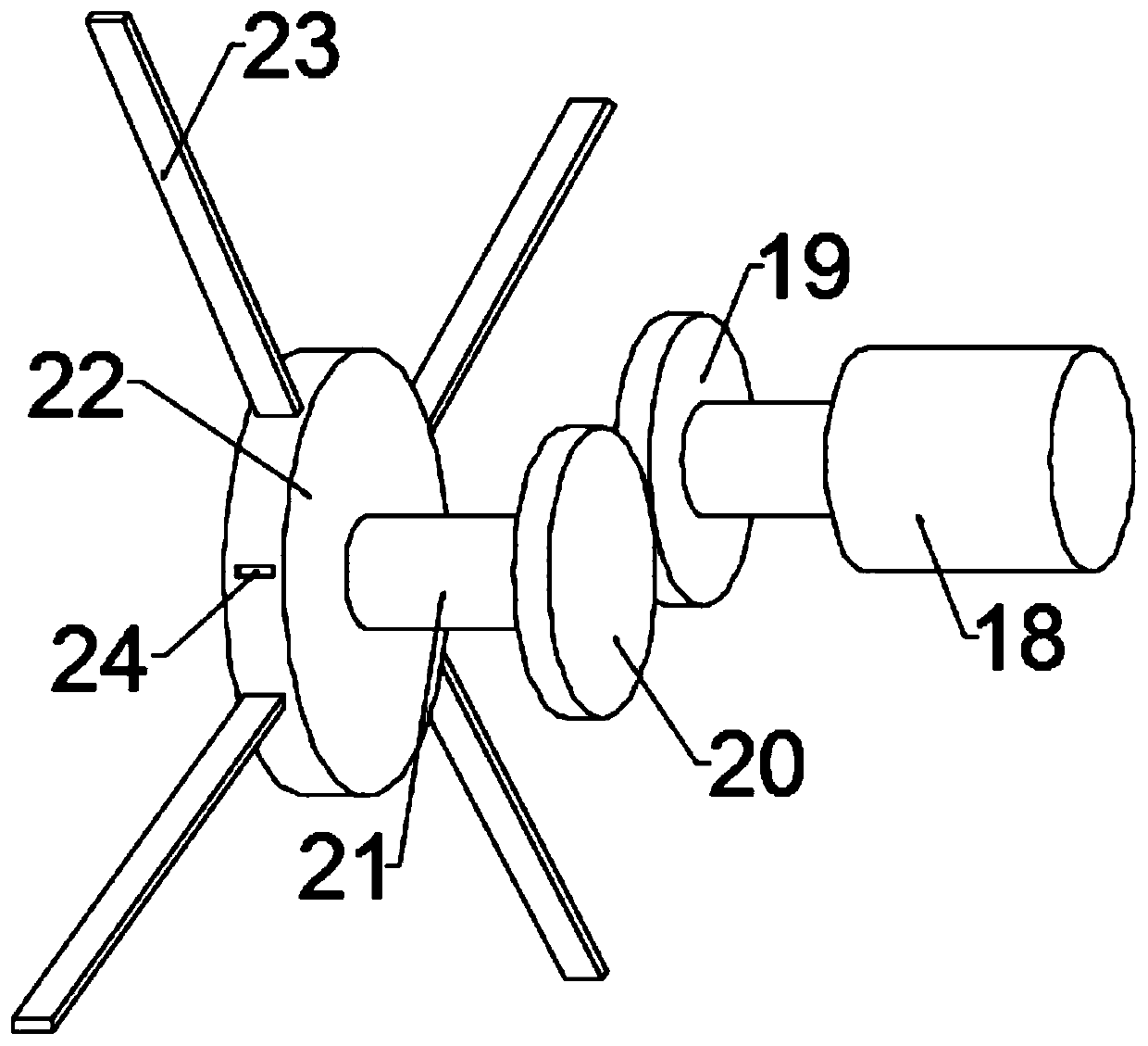
[0039] see Figure 1~2 , in an embodiment of the present invention, a kind of soap packaging machine feeding and conveying device comprises a soap collecting mechanism and a soap conveying mechanism, and the soap conveying mechanism is located directly below the soap collecting mechanism; the soap collecting mechanism includes a connected Square groove 1 and arc groove 2, described square groove 1 is provided with clamping assembly; Described soap delivery mechanism comprises transmission groove 8 and the transmission belt 10 that is installed in described transmission groove 8, in the transmission belt 10 A clamping component is provided; a cutting component and a waste collection mechanism are provided on both sides of the transmission slot 8 .

[0040] The feeding and conveying device of the soap packaging machine is different from the existing conveying device with a single function. It is specially equipped with a cutting assembly, which can cut excess soap to obtain fert...

Embodiment 2

[0056] see Figure 6 , in the embodiment of the present invention, a water tank 31 is provided at the bottom of the collection box 30, a heating wire 32 is installed inside the water tank 31, and a box cover 33 is installed at the top of the collection box 30, and the box cover 33 The lower surface of the electric push rod 34 is provided with a pressing plate 35 fixed on the bottom end of the electric push rod 34 .

[0057] After soap is collected in the inside of collecting box 30, open heating wire 32, the water in the tank 31 is heated, the soap in collecting box 30 inside softens after preheating, and case lid 33 is covered on the top of collecting box 30 again, starts electric motor The push rod 34, the electric push rod 34 controls the pressure plate 35 to push down until it is pressed on the soap, which is beneficial to repress the crumb-like soap into an available block, then close the heating wire 32, the water gradually cools, and the collection box 30 The soap in i...


PUM


Abstract

The invention relates to the technical field of soap processing, and particularly discloses a feeding and conveying device of a soap packaging machine. The feeding and conveying device comprises a soap collecting mechanism and a soap conveying mechanism, wherein the soap conveying mechanism is located right below the soap collecting mechanism, the soap collecting mechanism comprises a square groove and an arc groove which are connected, a clamping assembly is arranged on the square groove, the soap conveying mechanism comprises a conveying groove and a conveying belt installed in the conveyinggroove, a position clamping assembly is arranged in the conveying belt, and a cutting assembly and a waste collecting mechanism are arranged on two sides of the conveying groove. Different from an existing conveying device with a single function, the feeding and conveying device is particularly provided with the cutting assembly so that redundant soap can be cut, the soap with consistent size specification can be obtained, the soap connected together can be separated through the position clamping assembly to facilitate packaging, then, the waste collecting mechanism is used for collecting waste chips cut in the cutting process, and cleaning and sanitation of the feeding and conveying device are guaranteed.

Description

technical field [0001] The invention relates to the technical field of soap processing, in particular to a feeding and conveying device for a soap packaging machine. Background technique [0002] Soap is a general term for metal salts of fatty acids. It has a good effect of washing and decontaminating. It plays an important role in daily life and is a common daily necessities. The high-quality soap uses a conveyor belt to wrap a layer of wrapping paper on the body of the soap through a film-coating device, and then heat-seals and cuts both ends of the wrapping paper through a heat-sealing and cutting device to become an individually packaged soap for sale. [0003] But in the prior art, soap inevitably has size difference when cutting, and it is not easy to separate separately when being transported on the conveyor belt, and the quality of packaged soap varies. Contents of the invention [0004] The object of the present invention is to provide a soap packaging machine fe...

Claims


Application Information

Patent Timeline
Patent Type & Authority Applications(China)
IPC IPC(8): B65B35/50B65B35/24B26D1/09B26D7/18C11D13/18C11D13/12
CPCB26D1/09B26D7/18B65B35/24B65B35/50C11D13/12C11D13/30
Inventor 黄峻
Owner 安徽华谊日新科技有限公司
Learn More