
Suspension system for a wheeled vehicle and a wheeled vehicle equipped with such a suspension system

Inactive Publication Date: 2008-10-23
FONDAZIONE TORINO WIRELESS
View PDF8 Cites 88 Cited by
  • Summary
  • Abstract
  • Description
  • Claims
  • Application Information

AI Technical Summary

Benefits of technology

[0007]Moreover, it is an object of the present invention to provide a suspension system allowing to adequately and continuously vary the damping value or stiffness.
[0008]Still a further object of the present invention is that of providing a suspension system with reduced complexity.
[0009]Another object of the present invention is that of providing a suspension system offering an adequate compromise between cars handling and driving pleasure or comfort.
[0010]Still a further object of the present invention is that of providing a suspension system with no or few mechanical links, thus allowing optimizing of the packaging of the suspension system in a vehicle resulting in an improved layout of the overall vehicle.
[0012]Finally, a further object of the present invention is that of providing a suspension system wherein less friction arises than in a mechanical suspension system.
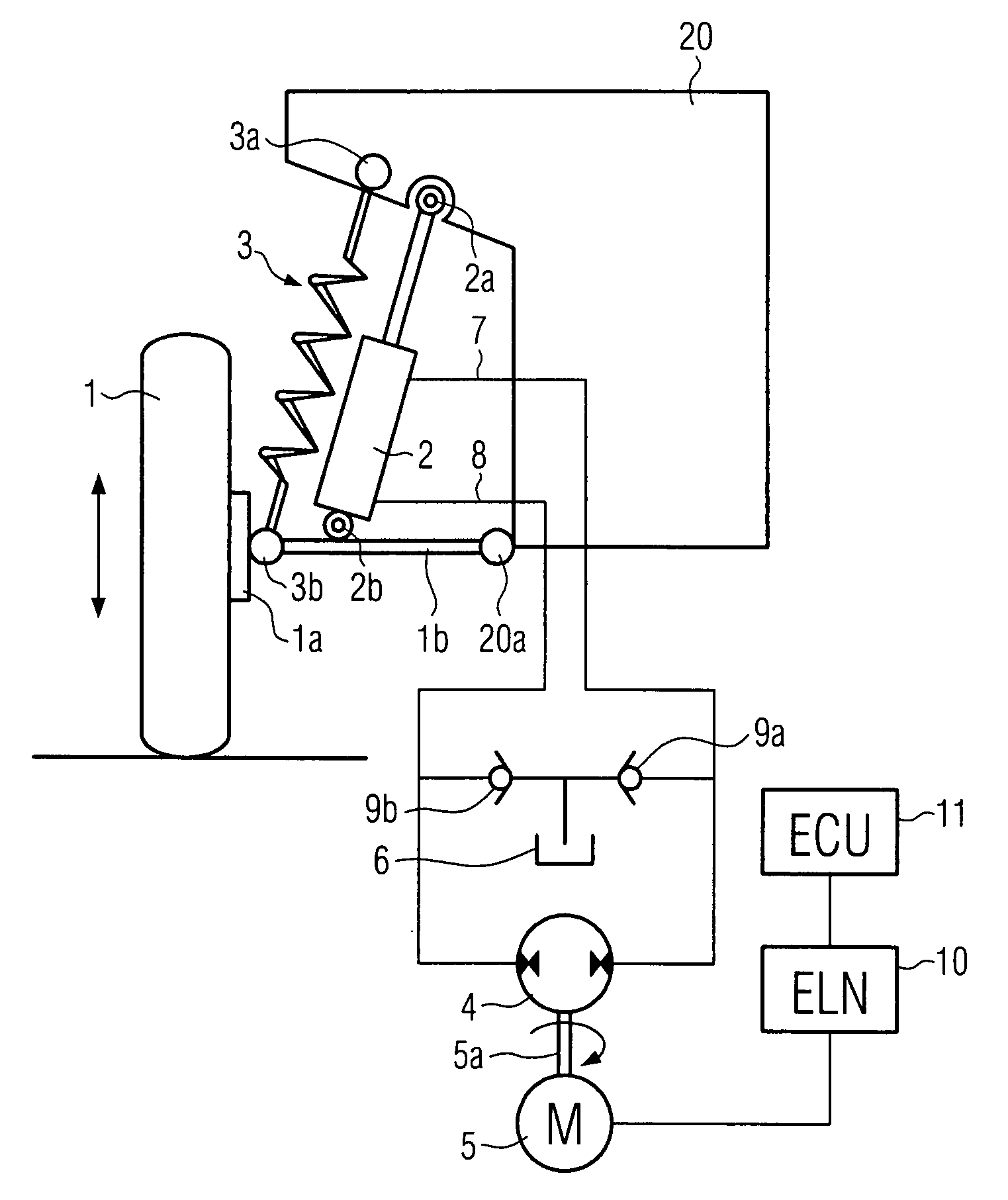
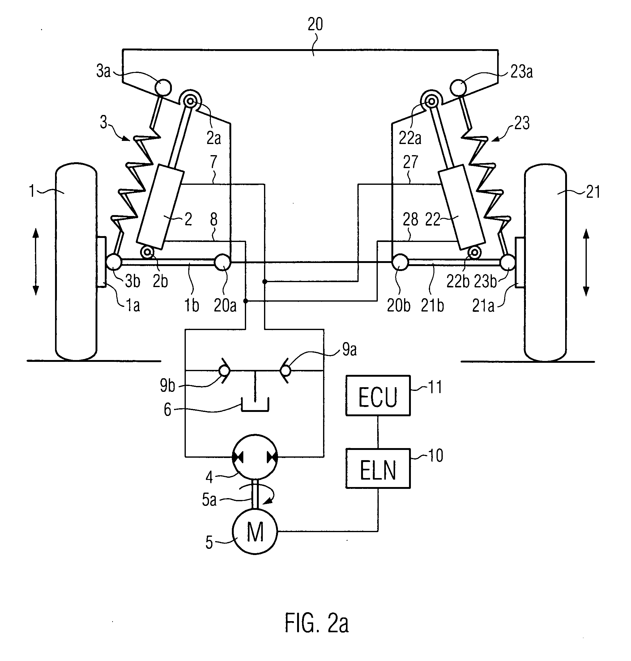
[0013]To this end, according to the present invention, this is obtained by providing a suspension system adapted to support at least one wheel of a vehicle and comprising shock absorbers coupled with electrical power generating means so that the shocks to which the wheel is subjected are used to generate electrical power and wherein the behavior of the shock absorbers may be varied as a function of the electrical power collected and / or dissipated. In other words, the possibility to generate electrical power and to collect and / or dissipate at least partially the electrical power generated allows control of the stiffness of the shock absorbers, thus obtaining the functionality of an active suspension system. Moreover, the electrical power absorbed may be easily controlled by means of controlling equipment so that neither additional mechanical links nor other complex equipments are required. Furthermore, the stiffness of two or more shock absorbers, for instance the two shock absorbers supporting wheels disposed on a common axle of the vehicle, may be controlled contemporarily, thus obtaining the function of a suspension system, wherein the wheels on a common axle behave the same way. Alternatively, the stiffness of each shock absorber of the vehicle may be controlled independently and separately, thus achieving the function of a fully independent suspension system, wherein each wheel behaves independently without affecting the other wheels of the vehicle. Moreover, and especially in those cases in which an electric motor is used for the purpose of generating electrical power, this electric motor may also be supplied with electrical power resulting in the possibility to also actuate the shock absorbers, thus obtaining the functionality of a fully active suspension system.

Problems solved by technology

They also must damp out much of the wheel bounce when the unsprung weight of a wheel, hub, axle and sometimes brakes and differential bounces up and down on the springiness of a tire.
However, developing suspension systems offering adequate performances has revealed to be a very difficult task for the car manufacturers.
In particular, this is due to the fact that the damping rate and stiffness of the suspension system drastically influences both safety and comfort of the vehicle.
However, in spite of all the advantages offered by active and semi-active suspension systems of the kind known in the art, these suspensions systems are still affected by several drawbacks.
In particular, the first very important disadvantage affecting the known suspension systems relates to the fact that the damping value or stiffness of these suspension systems may not be varied continuously.
Moreover, a further drawback affecting prior art suspension systems relates to the mechanical complexity and the small improvement in the driving performances and drive feeling that they allow under normal driving conditions so that their use is limited to high-end vehicles where higher costs may be justified.
Another drawback affecting both active and semi-active prior art suspension systems relates to the fact that these systems require very complicated electronic control devices.
Moreover, mechanical prior art suspension systems require a lot of space so that an ideal layout of the overall vehicle is quite often not possible.
Apart from complexity and the related costs the main drawback of the active suspensions is the amount of mechanical power they require from the vehicle engine.
An additional drawback of active solutions is the weight added to the vehicle and the need of a complex system to link the actuators installed in each suspension to the main power generation element usually installed as an accessory of the vehicle engine.

Method used


Image

  • Suspension system for a wheeled vehicle and a wheeled vehicle equipped with such a suspension system
  • Suspension system for a wheeled vehicle and a wheeled vehicle equipped with such a suspension system
  • Suspension system for a wheeled vehicle and a wheeled vehicle equipped with such a suspension system

Examples


Embodiment Construction

[0032]While the present invention is described with reference to the embodiments as illustrated in the following detailed description as well as in the drawings, it should be understood that the following detailed description as well as the drawings are not intended to limit the scope of the present invention to the particular illustrative embodiments disclosed, but rather the described illustrative embodiments merely exemplify the various aspects of the present invention, the scope of which is defined by the appended claims.

[0033]As apparent from the disclosure given above, the present invention is understood to be particularly advantageous when used for applications in the automotive field; in particular, the present invention is understood to be particularly advantageous when implemented in wheeled vehicles for the purpose of supporting the wheels of the vehicle and adequately absorbing the shocks to which the wheels are subjected during driving. For this reason, examples will be...


PUM


Abstract

A suspension system for a wheeled vehicle is provided, the suspension system being adapted to support at least one wheel of the vehicle and comprising at least one shock absorbing device adapted to be activated as a result of the motion of the at least one wheel in a substantially vertical direction, the suspension system further comprising electrical power generating means in fluid connection with the at least one shock absorbing device so that the activation of said at least one shock absorbing device results in electrical power being generated. Furthermore, the suspension system comprises means for absorbing at least partially the electrical power generated, the absorption of electrical power resulting in the stiffness of said at least one shock absorbing device being varied as a function of the electrical power absorbed.

Description

FIELD OF THE PRESENT INVENTION[0001]The present invention relates to the field of automotive applications. In particular, the present invention relates to a suspension system or module for wheeled vehicles and a wheeled vehicle equipped with such a suspension system or module. In more detail, the present invention relates to a suspension system or module adapted to support at least one wheel of a vehicle so as to adequately absorb shocks to which the at least one wheel may be subjected, for instance when crossing a bump or the like. Moreover, the present invention relates to a suspension system equipped with a shock absorbing device, wherein, during vertical displacement of the at least one wheel, the stiffness of the shock absorbing device may be actively varied according to the circumstances, such as, for instance, the driving conditions and / or as a result of driver commands. Still in more detail, the present invention relates to a suspension system or module, wherein the shock ab...

Claims


Application Information

Patent Timeline
IPC IPC(8): B60K25/10
CPCB60G13/14B60G17/0416B60G2202/416B60G2300/60F03G7/08
Inventor CARABELLI, STEFANOTONOLI, ANDREAFESTINI, ANDREACAVALLI, FABIOAMATI, NICOLA
Owner FONDAZIONE TORINO WIRELESS
Learn More