
Dust-free microwave vacuum drying device for optical lens resin raw material

A technology of microwave vacuum drying and resin raw materials, which is applied in the direction of drying gas arrangement, heating device, drying solid materials, etc., which can solve the problems of increasing the difficulty of guaranteeing the operation of the purification system, the inability to completely remove dust, and waste of raw materials.

Pending Publication Date: 2020-03-20
TIANJIN LAIWO VACUUM DRYING EQUIP MFG CO LTD
View PDF0 Cites 0 Cited by
  • Summary
  • Abstract
  • Description
  • Claims
  • Application Information

AI Technical Summary

Problems solved by technology

[0002] At present, when plastic optical resin is used for injection molding of mobile phone optical lens products, the optical resin raw material should be fully dried first. Traditional dryers use the circulation heating method of blowing hot air in the drying barrel + molecular sieve moisture absorption in the temperature range of 105°C-120°C. For more than 3 hours, better equipment will use nitrogen protection to prevent the water in the raw materials from hydrolyzing the plastic resin raw materials due to high temperature (250°C-280°C) during the injection molding process, which will cause the product to fail to meet the light distribution requirements.
In addition, factories that process mobile phone lenses are required to operate in a thousand-level cleanliness production environment. Because of the hot air circulation and molecular sieve regeneration factors of traditional dryers, the working principle determines that dust will be discharged into the workshop environment, and it is far more than a thousand-level purification workshop. requirements, which virtually increases the difficulty of guaranteeing the operation of the purification system, and is also an important factor in reducing the product qualification rate. However, no better drying method has been found to solve the problem.
[0003] In addition, during the drying process of traditional dehumidification dryers, powder and impurities will be brought into the raw materials due to the wear and tear of the moving parts of the fan when the hot air is blown and circulated. The absorption of these impurities in the raw materials will directly lead to the introduction of the raw materials into the product during the injection molding process, resulting in the decline of many high-demand optical technical indicators and resulting in the scrapping of the processed lens products.
The biggest quality defect of traditional dehumidification dryers is that the dust in the raw materials cannot be completely removed
[0004] What's more, during the packaging process of raw materials, static electricity will be generated due to collision and friction, which will absorb various fine pollutants (dust, oil and gas suspended matter, etc.) increased manufacturing costs
However, based on the existing application technology in the industry, traditional dehumidification dryers cannot completely separate the adsorbed dust and foreign matter that exist in the raw materials themselves. In addition, traditional dehumidification dryers must use long-term drying of raw materials (general optical materials need at least 120 ℃) Heating at high temperature for more than 3 hours) will also lead to the degradation of the raw material properties of fine dust, which will affect the optical properties of the product (oxidative yellowing). Long-term heating and drying methods will not only damage the physical and chemical properties of optical resin raw materials, but also cause The waste of energy is a common consensus among lens injection molding companies at present, and there is no better solution so far

Method used


Image

  • Dust-free microwave vacuum drying device for optical lens resin raw material

Examples


Embodiment Construction

[0036] The implementation mode of the present invention is illustrated by specific specific examples below, and those who are familiar with this technology can easily understand other advantages and effects of the present invention from the contents disclosed in this description. Obviously, the described embodiments are a part of the present invention. , but not all examples. Based on the embodiments of the present invention, all other embodiments obtained by persons of ordinary skill in the art without making creative efforts belong to the protection scope of the present invention.

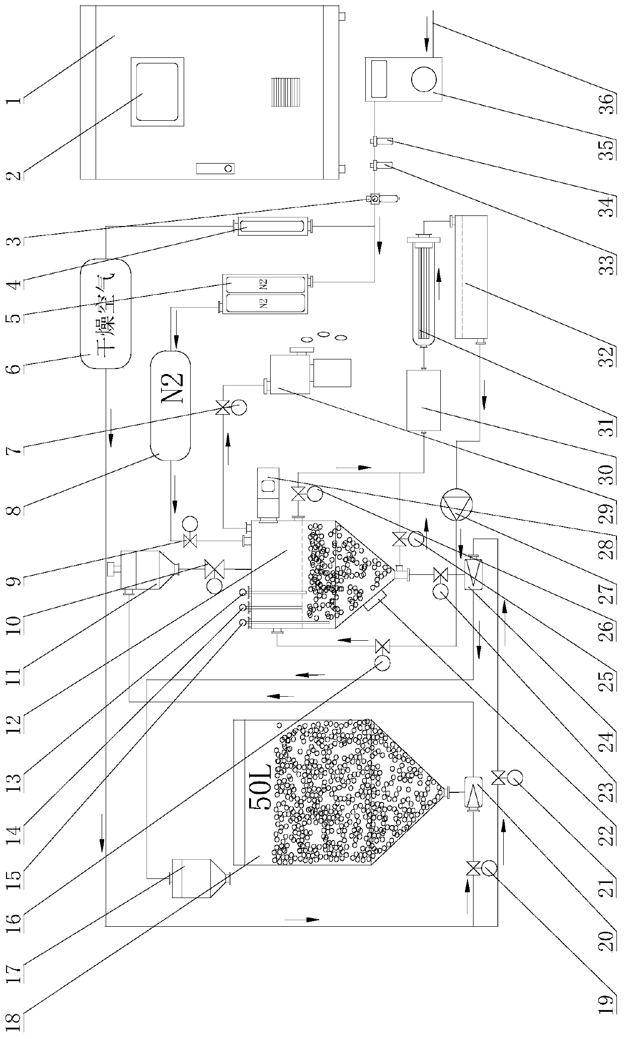
[0037] In order to solve the relevant technical problems existing in the prior art, the embodiment of the present application provides a dust-free microwave vacuum drying device for optical lens resin raw materials, which is mainly used for dust removal and drying of plastic optical resin injection molding raw material products for processing mobile phone optical lenses. dry. It includes a contr...


PUM


Abstract

The embodiment of the invention discloses a dust-free microwave vacuum drying device for an optical lens resin raw material. The device comprises a control cabinet, an air outlet end of an air supplymechanism is connected with a pressure regulating valve, the pressure regulating valve is connected with the air inlet end of a compressed air membrane separation dryer, and the air outlet end of thecompressed air membrane separation dryer is connected with the air inlet end of a dry air storage tank, and the air outlet of the dry air storage tank is connected with a feeding mechanism and a discharging mechanism; the feeding mechanism feeds raw materials to be dedusted and dried into an ultrasonic cleaning and drying chamber according to the venturi principle, and the discharging mechanism feeds the dedusted and dried raw materials into a re-suction preventive discharging hopper according to the venturi principle; and the raw materials are cleaned through deionized water cleaning liquid and an ultrasonic vibration generator, a vacuum pump and a microwave generator are started at the same time during drying, drying of the raw materials is accelerated, nitrogen is introduced into the ultrasonic cleaning and drying chamber after drying, and the raw materials are prevented from absorbing moisture again and being oxidized and yellowed. The raw materials are thoroughly cleaned, the drying speed is high, the effect is good, and no new pollution is introduced.

Description

technical field [0001] The embodiment of the present invention relates to the technical field of drying equipment, in particular to a dust-free microwave vacuum drying device for optical lens resin raw materials. Background technique [0002] At present, when plastic optical resin is used for injection molding of mobile phone optical lens products, the optical resin raw material should be fully dried first. Traditional dryers use the circulation heating method of blowing hot air in the drying barrel + molecular sieve moisture absorption in the temperature range of 105°C-120°C. For more than 3 hours, better equipment will use nitrogen protection to prevent the water in the raw materials from hydrolyzing the plastic resin raw materials due to high temperature (250°C-280°C) during the injection molding process, which will cause the product to fail to meet the light distribution requirements. . In addition, factories that process mobile phone lenses are required to operate in a...

Claims


Application Information

Patent Timeline
IPC IPC(8): F26B3/347F26B5/04F26B21/14F26B21/00F26B23/08B08B3/12B08B3/14B29B13/06
CPCF26B3/347F26B5/04F26B21/14F26B21/003B08B3/12B08B3/14B29B13/06
Inventor 李惠峰常晓宇刘健刘嘉平
Owner TIANJIN LAIWO VACUUM DRYING EQUIP MFG CO LTD
Learn More