Point source transmittance test system

A point source transmittance and test system technology, applied in the field of point source transmittance test systems of optical systems, can solve the problems affecting the PST test accuracy and access, and achieve the effect of strong test adaptability and improved test threshold.

Pending Publication Date: 2020-03-13
XI'AN INST OF OPTICS & FINE MECHANICS - CHINESE ACAD OF SCI
View PDF0 Cites 2 Cited by
  • Summary
  • Abstract
  • Description
  • Claims
  • Application Information

AI Technical Summary

Problems solved by technology

[0008] The purpose of the present invention is to provide a kind of point source transmittance test system, to solve the impact of the redundant laser energy column that enters through the light inlet of the test cavity on the PST test and the double cylindrical cavity structure at the angle of the measured camera test. When measuring in a non-horizontal direction, there is still a high probability that the reflected stray light will directly enter the entrance pupil of the camera, which will affect the accuracy of the PST test.

Method used


Image

  • Point source transmittance test system
  • Point source transmittance test system
  • Point source transmittance test system

Examples


Embodiment Construction

[0054] The present invention will be further described below in conjunction with the accompanying drawings and specific embodiments.

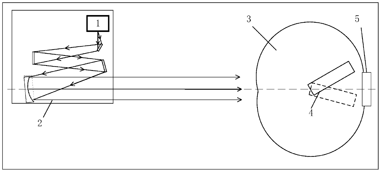
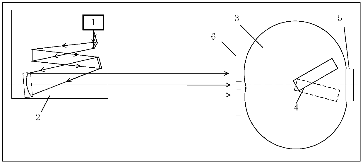
[0055] From figure 2 It can be seen that the point source transmittance testing system of this embodiment includes a light source, a collimator, an iris diaphragm and a test chamber sequentially arranged along the optical path, and the camera under test is located inside the test chamber.

[0056] The whole iris diaphragm of this embodiment is divided into two parts, wherein image 3 The concentric circle part shown is called "stack stop", and the square part is called "push-pull stop".

[0057] Such as Figure 4 , the laminated aperture mainly blocks the incident energy column by setting a series of concentric circular light holes, which is used to match the PST test of the test cameras with different calibers under the condition of small angle. In this embodiment, the laminated diaphragm includes five circular baffles, which are respectiv...


PUM

PropertyMeasurementUnit
surface roughnessaaaaaaaaaa

Abstract

The invention belongs to the field of optical system stray light test, and relates to a point source transmittance test system for an optical system in order to solve the problem that the PST test precision is affected by stray light. The point source transmittance test system comprises a light source, a collimator, a test cavity, and an iris diaphragm device arranged between a light outlet of thecollimator and a light inlet of the test cavity. A proper diaphragm size can be selected according to the aperture and the test angle of a tested camera, so as to shield an incident light column outside the test aperture and reduce the amount of radiated stray light. Meanwhile, a double-sphere cavity for testing the transmittance of a point source is designed, the cross section and the vertical section are the same as those of a double-cylinder cavity, and the sections of the cavity structure give consideration to the extinction advantages of the double-cylinder cavity at the same time in theaspects of azimuth and pitch, so that when the test angle of the camera is in a non-horizontal direction, stray light which can enter the camera after the reflected light of the inner wall of the cavity is reflected for multiple times can be almost neglected and is not limited at all, and stray light test is ensured to be carried out smoothly.

Description

technical field [0001] The invention belongs to the field of stray light testing of optical systems, and relates to a point source transmittance test system for optical systems, which can effectively shield ambient stray light during the point source transmittance test process and shield incident light columns outside the test aperture. Reduce the amount of stray light radiation. Background technique [0002] When the space optical system is in orbit, it is affected by stray light sources such as direct sunlight and diffuse reflection from the earth. Therefore, before it is put into operation, it must be tested on the ground to evaluate its ability to suppress stray light. Pass rate (PST) is a commonly used evaluation index at present. [0003] figure 1 It is the schematic diagram of the light path for the point source transmittance test. When the parallel light beam is incident on the light inlet of the camera, the signal obtained on the camera detection surface is not on...

Claims


Application Information

Patent Timeline
Patent Type & Authority Applications(China)
IPC IPC(8): G01M11/02
CPCG01M11/02
Inventor 李朝辉赵建科徐亮刘峰张玺斌李晓辉午建军刘勇毛振
Owner XI'AN INST OF OPTICS & FINE MECHANICS - CHINESE ACAD OF SCI
Why Eureka
Try Eureka