
Thermoelectric cooling device of inter-tube flowing working medium, with combination of flexible panel heat tube

A flat heat pipe and thermoelectric cooling technology, which is applied in the direction of refrigerators, indirect heat exchangers, heat exchange equipment, etc., can solve the problem of cooling of flowing working fluid, etc., and achieve the effect of easy disassembly and carrying, and good practical value

Inactive Publication Date: 2020-02-28
JIANGSU UNIV OF SCI & TECH
View PDF8 Cites 2 Cited by
  • Summary
  • Abstract
  • Description
  • Claims
  • Application Information

AI Technical Summary

Problems solved by technology

[0004] Purpose of the invention: The purpose of the invention is to provide a thermoelectric cooling device for the flowing working medium in the tube combined with a flexible flat heat pipe, which solves the cooling problem of the flowing working medium in the pipeline system

Method used


Image

  • Thermoelectric cooling device of inter-tube flowing working medium, with combination of flexible panel heat tube
  • Thermoelectric cooling device of inter-tube flowing working medium, with combination of flexible panel heat tube
  • Thermoelectric cooling device of inter-tube flowing working medium, with combination of flexible panel heat tube

Examples


Embodiment 1

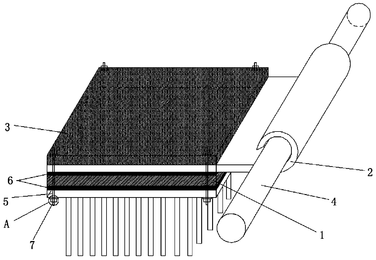
[0024] Such as figure 1 As shown, the present invention is a thermoelectric cooling device for working medium flowing in a tube combined with a flexible flat heat pipe, including a thermoelectric cooling sheet 1, the cold end of the thermoelectric cooling sheet 1 is attached to the lower surface of the condensation end of the flexible flat heat pipe 2, and the flexible flat heat pipe 2 The upper surface of the condensing end is bonded with a thermal insulation plate 3; one end of the flexible flat heat pipe 2 extends out of the thermoelectric cooling sheet 1 and the protruding end of the flexible flat heat pipe 2 has a curved structure, and the curved structure of the flexible flat heat pipe 2 is in line with the The copper pipe 4 is clamped and fixed, and the flexible flat heat pipe 2 can efficiently cool the working medium in the copper pipe 4; at the same time, the bending curvature of the curved structure of the flexible flat heat pipe 2 is set to be the same as that of the...

Embodiment 2

[0031] The difference between this embodiment and Embodiment 1 is that the cold end and the hot end of the thermoelectric cooling sheet 1 are reversed, that is, only the direction of the current in the thermoelectric cooling sheet 1 needs to be changed without disassembling the device. The present invention can be used for heating the copper pipe 4 .


PUM


Abstract

The invention discloses a thermoelectric cooling device of an inter-tube flowing working medium, with combination of a flexible panel heat tube. The thermoelectric cooling device comprises a thermoelectric cooling plate, wherein a cold end of the thermoelectric cooling plate is adhered on the lower surface of a condensation end of the flexible panel heat tube; the upper surface of the condensationend of the flexible panel heat tube is adhered to a thermal insulation plate; one end of the flexible panel heat tube extends out from the thermoelectric cooling plate, and the end part of an extending end of the flexible panel heat tube is of a bent structure; the bent structure of the flexible panel heat tube is clamped and fixed with a copper tube; a hot end of the thermoelectric cooling plateis fixedly connected to a heat radiator; and both the hot end and the cold end of the thermoelectric cooling plate are coated with a heat conductive silicon grease layer. The thermoelectric cooling device disclosed by the invention has the beneficial effects that through combination of the thermoelectric cooling plate with the flexible heat tube, the flowing working medium in the copper tube canbe cooled; the device is applicable to cooling of copper tubes with different tube diameters; the structure is simple and very convenient to dismount, carry and replace; and practical values are high.

Description

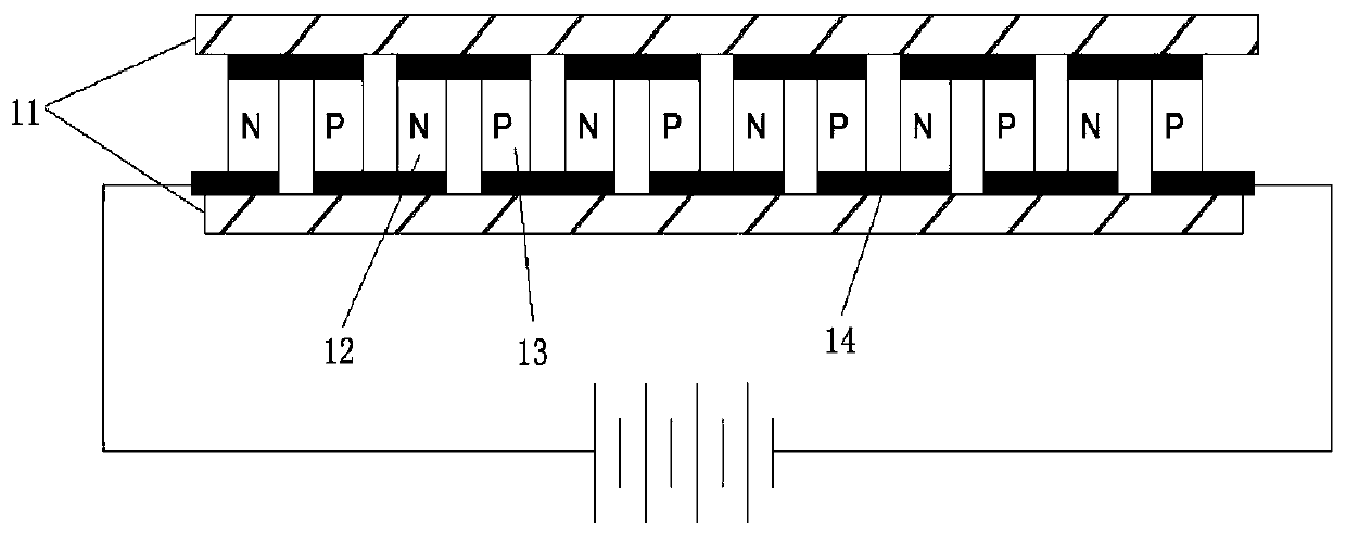
technical field [0001] The invention relates to the technical field of heat dissipation and cooling, in particular to a thermoelectric cooling device for working medium flowing in a tube combined with a flexible flat heat pipe. Background technique [0002] In the pipeline system, it is often necessary to cool and control the temperature of the flowing working medium in the pipe. At present, there is a lack of related products in the market. Generally, the heat exchanger is used to exchange heat between the flowing working medium and the external cooling water to reduce the temperature. The traditional refrigeration system has the disadvantages of difficult operation and complicated system. [0003] Refrigeration sheet is also called thermoelectric semiconductor refrigeration component, Peltier, etc. It refers to a patch that is divided into two sides, one side absorbs heat, the other side dissipates heat, and conducts heat. The thermoelectric cooling chip does not need any...

Claims


Application Information

Patent Timeline
IPC IPC(8): F25B21/02F28D15/02F28F21/08F28F3/02
CPCF25B21/02F28D15/02F28F3/02F28F21/084F28F21/085
Inventor 王雷青张东辉徐海洋陈一
Owner JIANGSU UNIV OF SCI & TECH
Learn More