
An outer ring grinding device for drive shaft assembly processing

A drive shaft and grinding technology, which is applied to grinding drive devices, grinding/polishing safety devices, metal processing equipment, etc. The scope of use, the scope of application, and the effect of good sound insulation

Active Publication Date: 2021-06-01
芜湖佳先传动轴有限公司
View PDF11 Cites 0 Cited by
  • Summary
  • Abstract
  • Description
  • Claims
  • Application Information

AI Technical Summary

Problems solved by technology

[0002] Patent document CN104551884B discloses a centerless grinding device, including a main machine with a base, a grinding wheel, a guide wheel and a workpiece support plate; the grinding wheel and the guide wheel cooperate to form a grinding channel; the centerless grinding device also includes a feeding Device; the feeding device includes a vibrating plate with a discharge port, a slanted feed pipe connected to the high end with the discharge port, and a vertical feed pipe connected to the lower end of the slanted feed pipe at the upper end, located on the front side of the vertical feed pipe A material guide tube with a material guide hole and a material pushing device located at the rear side of the vertical lower material tube; the front side of the lower end of the vertical lower material tube is connected to one end of the material guide tube and is provided with a discharge hole communicated with the material guide hole; The other end of the material tube is opposite to the grinding channel; the rear side of the lower end of the vertical material tube is provided with a material pushing hole opposite to the material pushing device. ring
[0003] The existing outer ring grinding device has certain disadvantages in the process of use. The traditional outer ring grinding device does not have a snap ring adjustment structure. When the user needs to perform grinding operations on outer rings of different sizes, the outer ring must be The parts of the grinding device are replaced, which reduces the scope of application of the equipment; secondly, the traditional outer ring grinding device does not have a dust removal structure, and metal dust is easily generated during the grinding process of the outer ring grinding device, which increases the It is difficult to clean the equipment; at the same time, the traditional outer ring grinding device adopts the sliding method to add materials. Compared with the rolling method, the friction force of sliding is greater, which increases the degree of wear of the equipment and brings certain adverse effects to users.

Method used


Image

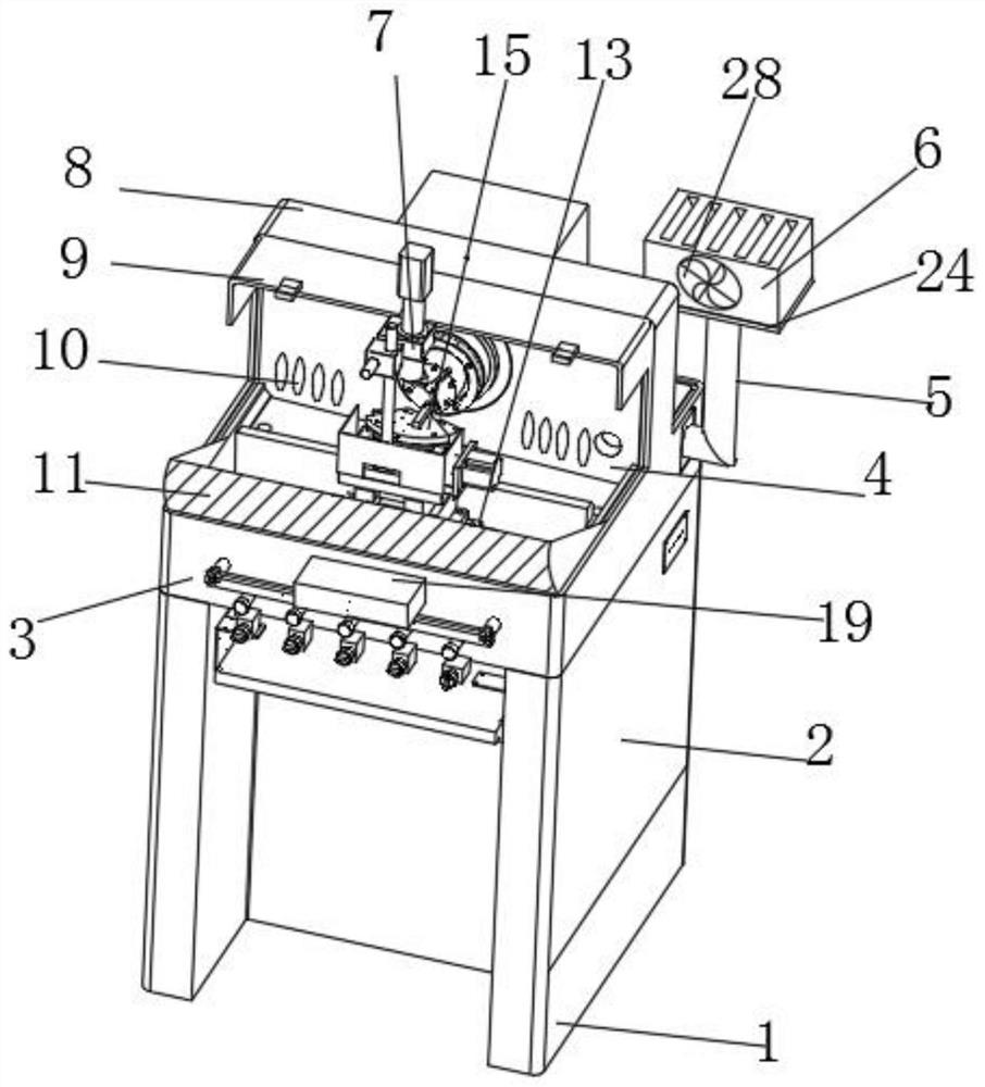
  • An outer ring grinding device for drive shaft assembly processing
  • An outer ring grinding device for drive shaft assembly processing
  • An outer ring grinding device for drive shaft assembly processing

Examples


Embodiment Construction

[0035] The technical solutions in the embodiments of the present invention will be clearly and completely described below in conjunction with the embodiments of the present invention. Apparently, the described embodiments are only some of the embodiments of the present invention, not all of them. Based on the embodiments of the present invention, all other embodiments obtained by persons of ordinary skill in the art without creative efforts fall within the protection scope of the present invention.

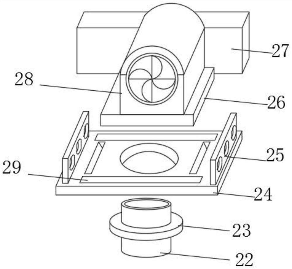
[0036] Such as Figure 1-6 As shown, an outer ring grinding device for drive shaft assembly processing includes a processing platform 3, a grinding table 7, a sealing bottom plate 24, a feeding card holder 19, a grinding head 32, a turning shield 11 and a grinding rotating rod 20. The grinding table 7 is installed on the upper part of the processing platform 3, and the grinding table 7 and the processing platform 3 are docked and fixed through the splicing base 13, and the grindin...


PUM


Abstract

The invention discloses an outer ring grinding device for drive shaft assembly processing, which includes a processing platform, a grinding table, a sealing bottom plate, a feeding card frame and a grinding rotating rod. The grinding table is installed on the upper part of the processing platform, and The grinding table and the processing platform are docked and fixed by a splicing base. Two sets of limit snap rings are fixedly installed on the upper part of the splice base, and splicing snap rings are fixedly installed on the outer surface of the upper end of the limit snap ring. The outer surface of the upper part of the snap ring is fixedly sleeved with a side guard, and the limit snap ring and the side guard are docked and fixed through a slot, and a supporting ejector rod is fixedly installed under the grinding rotating rod; a The outer ring grinding device used for the processing of the drive shaft assembly can make the outer ring grinding device have a bayonet adjustment structure, increase its application range, reduce the wear of the outer ring grinding device during use, and make its internal cleaning operation It is more convenient and prolongs its service life.

Description

technical field [0001] The invention belongs to the technical field of drive shaft processing, and in particular relates to an outer ring grinding device, in particular to an outer ring grinding device for drive shaft assembly processing. Background technique [0002] Patent document CN104551884B discloses a centerless grinding device, including a main machine with a base, a grinding wheel, a guide wheel and a workpiece support plate; the grinding wheel and the guide wheel cooperate to form a grinding channel; the centerless grinding device also includes a feeding Device; the feeding device includes a vibrating plate with a discharge port, a slanted feed pipe connected to the high end with the discharge port, and a vertical feed pipe connected to the lower end of the slanted feed pipe at the upper end, located on the front side of the vertical feed pipe A material guide tube with a material guide hole and a material pushing device located at the rear side of the vertical low...

Claims


Application Information

Patent Timeline
Patent Type & Authority Patents(China)
IPC IPC(8): B24B19/11B24B27/00B24B41/06B24B45/00B24B47/00B24B47/12B24B47/22B24B55/04B24B55/06B24B55/12
CPCB24B19/11B24B27/0069B24B41/067B24B45/003B24B47/00B24B47/12B24B47/22B24B55/04B24B55/06B24B55/12
Inventor 吴望才
Owner 芜湖佳先传动轴有限公司
Learn More