
A pressure monitoring device

A pressure monitoring and pressure technology, used in measuring devices, blood transfusion devices, measuring fluid pressure, etc., can solve the problems of centrifugal cup rupture, cracking, safety accidents, etc., and achieve good sealing reliability, accurate monitoring, and high reliability.

Active Publication Date: 2021-07-23
SICHUAN NIGALE BIOTECH
View PDF6 Cites 0 Cited by
  • Summary
  • Abstract
  • Description
  • Claims
  • Application Information

AI Technical Summary

Problems solved by technology

If the pressure in the pipeline is too high, it may cause the rupture of the centrifuge cup and the physical discomfort of the blood donor, and even cause a safety accident; if the pressure in the pipeline is too low, it indicates that the blood pressure of the blood donor is low, and the blood donor is not suitable for high-speed To collect blood, at this time, the peristaltic pump needs to reduce the pump speed in time to ensure the safety of blood donors and the normal progress of blood separation
However, during the use of existing pressure monitoring devices, problems such as rubber aging and cracking generally exist, which seriously affect the normal use of the pressure monitoring device; at the same time, between the air interface of the pressure monitoring device and the pressure joint of the blood collection tube There are also problems such as poor sealing, so that the pressure monitoring device cannot detect changes in the pressure in the pipeline; in addition, when installing the pressure connector of the blood collection tube, the operator needs to use a lot of force to install it in place, and the long-term operation will inevitably cause damage. Causes the operator to be easily fatigued, thereby increasing the labor intensity of the operator

Method used


Image

  • A pressure monitoring device
  • A pressure monitoring device

Examples


Embodiment Construction

[0019] In order to make the object, technical solution and advantages of the present invention clearer, the present invention will be described in detail below in conjunction with the accompanying drawings and specific embodiments. It should be understood that the specific embodiments described here are only used to explain the present invention, not to limit the present invention.

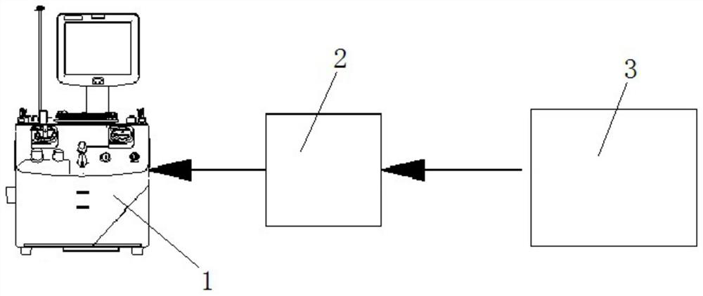
[0020] Such as figure 1 The blood component separator pressure monitoring system shown mainly includes a blood component separator 1, a controller 2 and a pressure monitoring device 3, the pressure monitoring device 3 is provided with a pressure sensor transducer 13, and the controller 2. PLC or MCU is usually used, and the controller 2 is electrically connected to the blood component separator 1 and the pressure sensor transducer 13 respectively. A sealed connection structure is formed between the pressure monitoring device 3 and the blood collection tube, specifically, a sealed connection struc...


PUM


Abstract

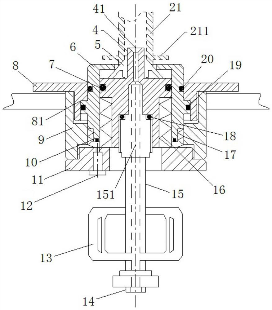
The invention provides a pressure monitoring device, comprising a joint piston (4), a positioning piston (6), a pressure sensing transducer (13) and an air plunger (15), and a joint channel (41) is formed on the joint piston (4) ), an air channel (151) is formed on the air plunger (15); a static sealing structure is formed between the joint piston (4) and the air plunger (15), and the joint piston (4) is positioned by combining the seal (5) with the A dynamic sealing structure is formed between the pistons (6), the joint channel (41) communicates with the air channel (151) to form a fluid channel, and the pressure sensing transducer (13) collects and outputs the pressure signal of the fluid channel. By using the piston component as the moving part, the invention can ensure the flexible action and good sealing reliability of the pressure monitoring device, thereby accurately monitoring the pressure change in the pipeline, and has outstanding advantages such as simple structure and high pressure monitoring reliability.

Description

technical field [0001] The invention relates to the field of pipeline pressure monitoring, in particular to a pressure monitoring device applied to a blood component separator system. Background technique [0002] Human blood is divided into a plasma layer, a buffy coat layer, and a red blood cell layer according to different densities. Among them, the buffy coat layer can be divided into a platelet layer and a white blood cell layer. Among these blood components, the least dense is the plasma layer, and the densest is the erythrocyte layer. It is precisely according to the density of blood components that blood can be divided into different components by centrifugation technology, so as to realize the apheresis of blood components, such as apheresis of plasma, apheresis of platelets, and apheresis of red blood cells. [0003] In the process of using a blood component separator to separate whole blood, it is necessary to use a pressure monitoring device to monitor the press...

Claims


Application Information

Patent Timeline
Patent Type & Authority Patents(China)
IPC IPC(8): G01L11/00A61M1/02A61M1/38
CPCA61M1/0272A61M1/38G01L11/00
Inventor 王朝富李川陈石
Owner SICHUAN NIGALE BIOTECH
Learn More