
Drainage pipe network monitoring system

A drainage pipe network and monitoring system technology, applied in the field of drainage monitoring, can solve the problems of unclear operation and maintenance conditions, the actual drainage capacity of the pipe network, the specific situation of the concentration of toxic gases, and the imperfect urban underground drainage pipe network system. The effect of strengthening management and improving the level of operation and maintenance

Inactive Publication Date: 2020-02-14
重庆市市政设计研究院有限公司
View PDF12 Cites 5 Cited by
  • Summary
  • Abstract
  • Description
  • Claims
  • Application Information

AI Technical Summary

Problems solved by technology

However, the long-term existence of "emphasis on the ground, less on the underground" and "emphasis on construction and less on management" has led to the imperfection of the urban underground drainage network system, and the unknown status of the pipe network, especially the operation and maintenance situation, has become a bottleneck for improving the quality and efficiency of the drainage system. The confluence of rain and sewage, the confluence of cleaning and sewage, the siltation of pipes and canals, the overflow of sewage, the damage of pipe networks, the actual drainage capacity of pipe networks, the concentration of toxic gases, etc. are not clear. An important restrictive factor for the improvement of urban water safety. Therefore, it is urgent to establish a feasible monitoring index system to grasp the operating conditions of pipelines in a timely manner and scientifically guide the normal operation of pipelines.

Method used


Image

  • Drainage pipe network monitoring system
  • Drainage pipe network monitoring system
  • Drainage pipe network monitoring system

Examples


Embodiment Construction

[0024] Embodiments of the present invention are described in detail below, examples of which are shown in the drawings, wherein the same or similar reference numerals designate the same or similar elements or elements having the same or similar functions throughout. The embodiments described below by referring to the figures are exemplary only for explaining the present invention and should not be construed as limiting the present invention.

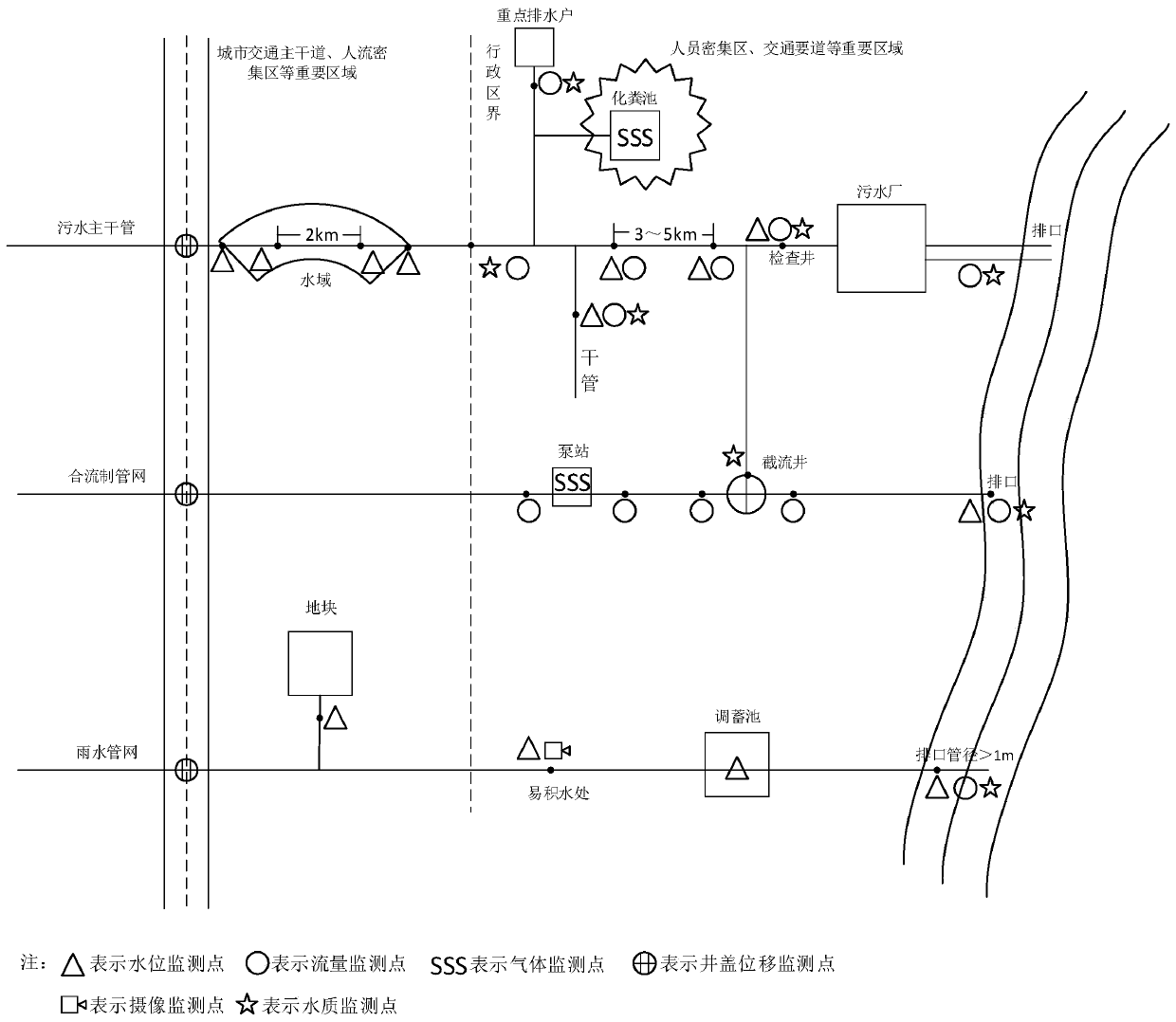
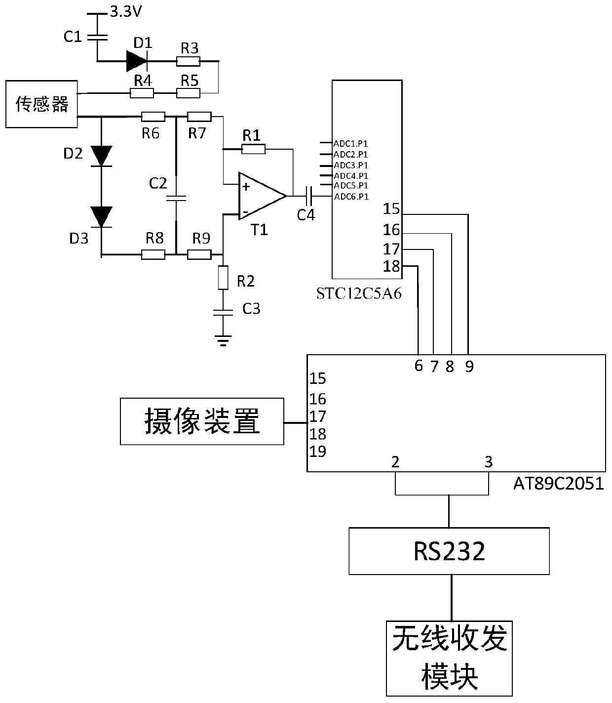
[0025] The invention discloses a drainage pipe network monitoring system, such as figure 1 and figure 2 As shown, including: setting water level, flow, and water quality monitoring points at key nodes of the sewage pipe network, rainwater pipe network, and combined pipe network; Set up gas monitoring points at sewage pipe networks and septic tanks where there are dense populations and easy to gather toxic, harmful, flammable and explosive gases, and set up pipeline structure safety inspection points at places with structural safety ris...


PUM


Abstract

The invention provides a drainage pipe network monitoring system. The drainage pipe network monitoring system is constructed in the aspects of water level, water quantity, water quality, gas, mud deposition depth, pipeline structure safety, well lid displacement, video monitoring and the like. The drainage pipe network monitoring system comprises water level, flow and water quality monitoring points arranged at key nodes of a sewage pipe network, a rainwater pipe network and a combined pipe network, mud deposition depth monitoring points arranged at key nodes of a pipeline network with low gradient, low flow speed and the like, gas monitoring points arranged at the sewage pipe network and a septic tank where people are dense and poisonous, harmful, flammable and explosive gas is prone to being gathered, pipeline structure safety monitoring points arranged at the positions with structural safety risks such as road surface settlement and landslide, well lid displacement monitoring pointsarranged in important areas such as crowded areas and areas prone to overflowing, and video monitoring points arranged at the positions prone to waterlogging such as lower through channels, tunnels and sunken squares. The drainage pipe network monitoring system achieves system monitoring of a drainage pipe network.

Description

technical field [0001] The invention relates to the field of drainage monitoring, in particular to a drainage pipe network monitoring system. Background technique [0002] With the rapid development of urbanization, all aspects of facilities are gradually improved. However, the long-term existence of "emphasis on the ground, less on the underground" and "emphasis on construction and less on management" has led to the imperfection of the urban underground drainage network system, and the unknown status of the pipe network, especially the operation and maintenance situation, has become a bottleneck for improving the quality and efficiency of the drainage system. The confluence of rain and sewage, the confluence of cleaning and sewage, the siltation of pipes and canals, the overflow of sewage, the damage of pipe networks, the actual drainage capacity of pipe networks, the concentration of toxic gases, etc. are not clear. It is an important restrictive factor for the improvemen...

Claims


Application Information

Patent Timeline
IPC IPC(8): G01D21/02G01N33/18
CPCG01D21/02G01N33/18
Inventor 蒲贵兵吕波刘杰向星光蔡岚董佳苏定江刘希
Owner 重庆市市政设计研究院有限公司
Learn More