
Circuit board printing device

A printing device and circuit board technology, applied in printing, printing machines, printed circuits, etc., can solve the problems of long drying time, non-concentrated heat, heat dissipation, etc., and achieve the effect of increasing drying efficiency

Pending Publication Date: 2020-02-14
SUZHOU HUILIYUAN TECH CO LTD
View PDF0 Cites 6 Cited by
  • Summary
  • Abstract
  • Description
  • Claims
  • Application Information

AI Technical Summary

Problems solved by technology

[0004] The purpose of the present invention is to provide a circuit board printing device to solve the problem of heat dissipation during the drying process proposed in the above background technology, and the heat is not concentrated on the printing part, resulting in long drying time.

Method used


Image

  • Circuit board printing device
  • Circuit board printing device
  • Circuit board printing device

Examples


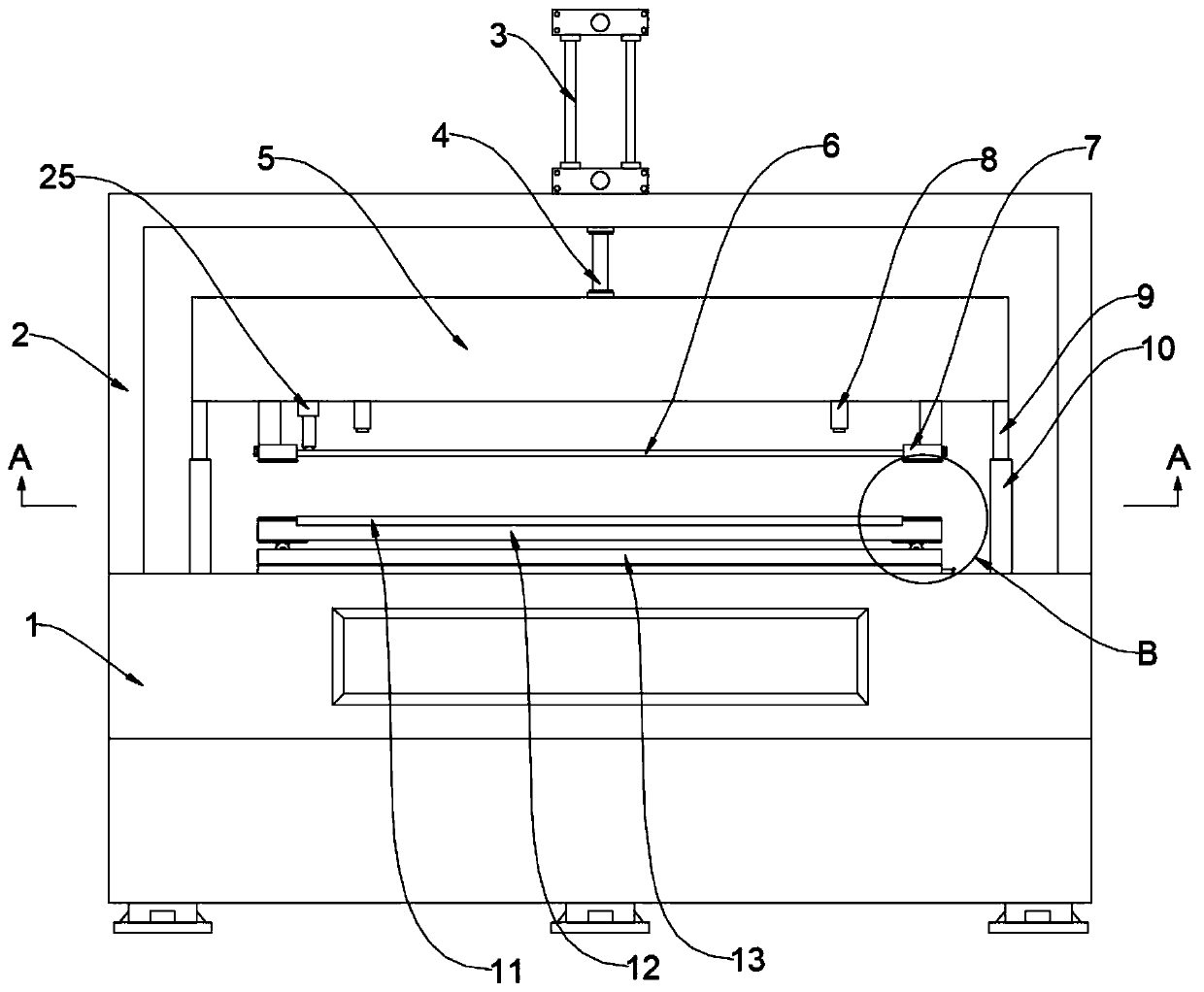
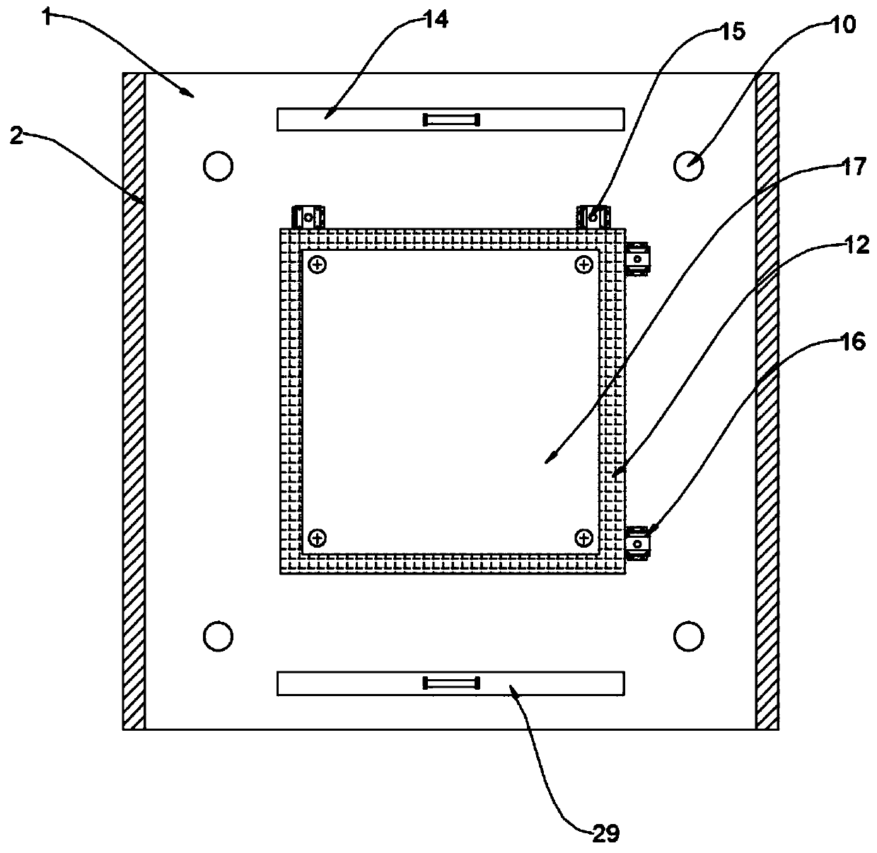
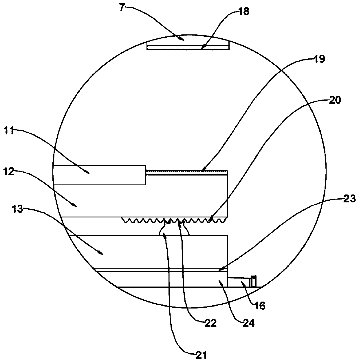
Embodiment Construction

[0027] The following will clearly and completely describe the technical solutions in the embodiments of the present invention with reference to the accompanying drawings in the embodiments of the present invention. Obviously, the described embodiments are only some, not all, embodiments of the present invention.

[0028] see Figure 1-8, an embodiment provided by the present invention: a circuit board printing device, including a workbench 1, a first drying device 14 is installed in the middle of the upper end surface of the workbench 1, and a second drying device 14 is installed in the middle of the upper end surface of the workbench 1. drying device 29, and the first drying device 14 and the second drying device 29 are all connected with the workbench 1 by the slide bar 32, the slide bar 32 can be replaced by the current electric control guide rail, so that it can be operated automatically, and if It is an electric control guide rail, and the electric control guide rail need...


PUM


Abstract

The invention discloses a circuit board printing device, and relates to the related field of circuit board printing. The problem that in the prior art, in the drying process, heat is dissipated, heatis not concentrated on the printing portion, and consequently, drying time is long can be solved. The middle of the rear end of the upper end face of a worktable is provided with a first drying device, a second drying device is arranged in the middle of the front end of the upper end face of the worktable, the first drying device and the second drying device are connected with the worktable through sliding strips, the first drying device and the second drying device are embedded in the worktable, and the first drying device and the second drying device each comprise an outer frame, a placing groove, a connecting telescopic rod, a drying plate, a moving groove, a drying area, a drying device supporting plate and a pressure spring.

Description

technical field [0001] The invention relates to the related field of circuit board printing, in particular to a circuit board printing device. Background technique [0002] Usually on the insulating material, according to the predetermined design, the conductive pattern made of printed circuit, printed component or a combination of the two is called printed circuit. The conductive pattern that provides electrical connection between components on an insulating substrate is called a printed circuit. In this way, the finished board of printed circuit or printed circuit is called printed circuit board, also known as printed board or printed circuit board. Ink printing in the production process of printed circuit boards can be divided into photosensitive line ink printing, solder resist ink and character ink printing, among which photosensitive line ink printing is full-page printing, and there is no requirement for graphic alignment. Therefore, the screen printing machine suit...

Claims


Application Information

Patent Timeline
Patent Type & Authority Applications(China)
IPC IPC(8): B41F23/04B41F15/12H05K3/12H05K3/22
CPCB41F15/12B41F23/044H05K3/1216H05K3/227
Inventor 仇海艳
Owner SUZHOU HUILIYUAN TECH CO LTD
Learn More