Cylindrical glass product mechanical clamping arm with two-degree-of-freedom adjustment and control method thereof

A technology of glass products and degrees of freedom, which is applied in the direction of program-controlled manipulators, manipulators, chucks, etc. It can solve the problem that position positioning and speed control cannot meet the requirements of high speed and large output, and the opening angle of the clamps of the bottle body cannot be adjusted. Problems such as opening and closing time points, inaccurate cylinder and hydraulic drive, etc., to avoid instability and non-adjustability of cam control clamping, accurate and free control, and good repeatability

Pending Publication Date: 2020-02-14
GUANGDONG PFANNENBERG TECH CO LTD
View PDF0 Cites 1 Cited by
  • Summary
  • Abstract
  • Description
  • Claims
  • Application Information

AI Technical Summary

Problems solved by technology

[0003] However, most of the mechanical arms in the prior art use cylinders or hydraulically driven mechanical arms. The cylinders and hydraulic drives are not accurate, and the position positioning and speed control cannot meet the requirements of high speed and large output (such as 300 pieces / minute).
At the same time, the mechanical arm in the prior art can only hold one glass bottle, and the length and running track of the mechanical arm need to be designed in advance according to the production line, and cannot be adjusted at will after being manufactured. If adjustment is required, the mechanical parts can only be redesigned and replaced.
[0004] Moreover, the existing glass bottle clamps control the time point and opening angle position of opening and closing through the cam mechanism cycle, and can only clamp the bottle body of a certain diameter, and cannot be adjusted according to the diameter of the bottle body or the unevenness of the bottle body. Shapes such as curves and elliptical contours are used to adjust the opening angle and opening and closing time of the clamps of the bottle body

Method used


Image

  • Cylindrical glass product mechanical clamping arm with two-degree-of-freedom adjustment and control method thereof
  • Cylindrical glass product mechanical clamping arm with two-degree-of-freedom adjustment and control method thereof
  • Cylindrical glass product mechanical clamping arm with two-degree-of-freedom adjustment and control method thereof

Examples


Embodiment Construction

[0028] The present invention will be described in detail below in conjunction with the accompanying drawings and specific embodiments.

[0029] In the description of the present invention, it should be understood that the orientation or positional relationship indicated by the terms "upper", "lower", "front", "rear", "left", "right" etc. are based on those shown in the accompanying drawings. Orientation or positional relationship is only for the convenience of describing the present invention and simplifying the description, and does not indicate or imply that the referred device or element must have a specific orientation, be constructed and operated in a specific orientation, and thus should not be construed as a limitation of the present invention.

[0030]In addition, the terms "first", "second", "third" and "fourth" are used for descriptive purposes only, and should not be construed as indicating or implying relative importance or implicitly specifying the number of techni...


PUM


Abstract

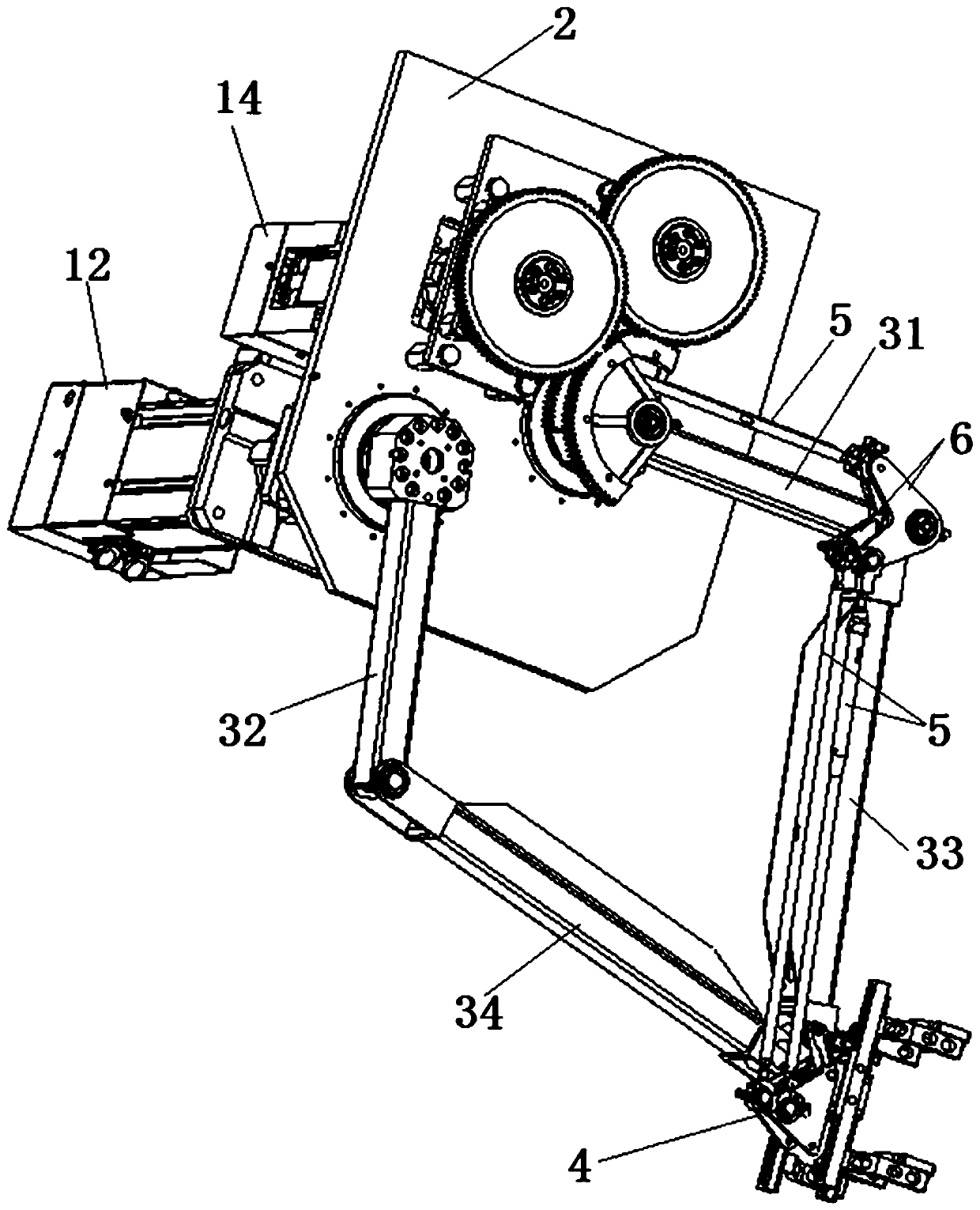
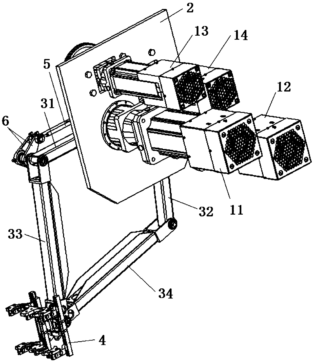
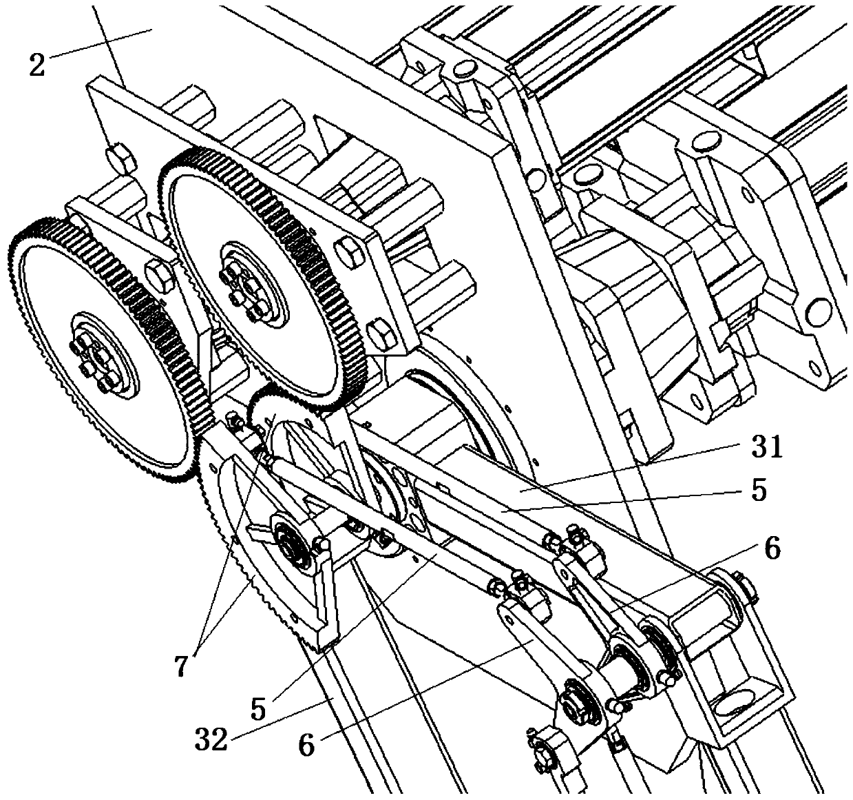
The invention provides a cylindrical glass product mechanical clamping arm with two-degree-of-freedom adjustment. The cylindrical glass product mechanical clamping arm with two-degree-of-freedom adjustment comprises a driving motor, a motor fixing plate, an action arm and a glass bottle clamp, wherein the driving motor comprises a front driving arm driving motor and a rear driving arm driving motor; a front driving arm and a rear driving arm of a glass bottle clamp are respectively connected and driven by the front driving arm driving motor and the rear driving arm driving motor; a specific track is obtained through the mutual matching of the quadrangular driving arms; different glass bottle clamp movement tracks can be designed by adjusting the running speed, the angle and the relative position of the two driving arms, so that different production lines is adapted; and in addition, the swing and the clamping of the glass bottle clamp are controlled through the transmission of a servomotor and a gear, so that the clamping time point, the opening angle and the position of the glass bottle clamp is freely controlled, and the glass bottle clamp is suitable for cylindrical glass products such as glass bottles and cups with different specifications. The cylindrical glass product mechanical clamping arm with two-degree-of-freedom adjustment has the advantages of adjustable track, accurate control and suitability for cylindrical glass products with various specifications.

Description

technical field [0001] The invention belongs to the field of automatic cylindrical glass product production equipment, and in particular relates to a dual-degree-of-freedom adjustable cylindrical glass product mechanical clamping arm, and also relates to a control method of the mechanical clamping arm. Background technique [0002] At present, the production of glass bottles tends to be large-volume and various in shape design, which makes the bottle clamping mechanism and action requirements of the robot arm must be designed in the direction of flexibility and high speed, and needs to adapt to different bottle shapes. In addition, the current production trend has certain technical requirements for equipment capacity, repeat positioning accuracy, flexible setting of the starting position of the upper and lower bottles, etc. [0003] However, most of the mechanical arms in the prior art use cylinders or hydraulically driven mechanical arms. The cylinders and hydraulic drives ...

Claims


Application Information

Patent Timeline
Patent Type & Authority Applications(China)
IPC IPC(8): B25J9/00B25J9/10B25J9/12B25J15/02B25J15/08
CPCB25J9/00B25J9/10B25J9/126B25J15/0206B25J15/08
Inventor 陈旺
Owner GUANGDONG PFANNENBERG TECH CO LTD
Why Eureka
Try Eureka