Forming process of conveyor belt

A molding process and conveyor belt technology, applied in belts, other household appliances, household appliances, etc., can solve the problems of heat resistance, increased traction, waste, etc., and achieve the effect of not easy to slip, improve service life, and save financial resources.

Active Publication Date: 2020-02-11
湖南宝烽设备股份有限公司
View PDF12 Cites 1 Cited by
  • Summary
  • Abstract
  • Description
  • Claims
  • Application Information

AI Technical Summary

Problems solved by technology

[0002] The conveyor belt is a belt installed on the conveyor to carry and convey materials. It consists of three parts, namely the belt core, the core rubber material and the cover rubber, which is the surface layer of the belt. The role of the cover rubber is mainly to protect the skeleton, transmit power and Conveying materials, resisting material wear, impact, corrosion, heat resistance, acid resistance, increasing traction and controlling materials to meet the function of conveying different substances. The traditional conveyor belt forming process route is to calender canvas and cover rubber on the calender respectively, and coil For standby, after laminating the calendered glued canvas on the forming machine according to the process requirements, the semi-finished belt embryo is made by laminating the side glue and the upper and lower covering glue on the molding machine or calender. This process makes the supporting belt embryo a whole structure, if part of the cover rubber is worn, broken or corroded during the transmission process, the entire conveyor belt needs to be replaced, which is wasteful. For this reason, we propose a conveyor belt molding process

Method used


Image

  • Forming process of conveyor belt
  • Forming process of conveyor belt

Examples


Embodiment Construction

[0028] The following will clearly and completely describe the technical solutions in the embodiments of the present invention with reference to the accompanying drawings in the embodiments of the present invention. Obviously, the described embodiments are only some, not all, embodiments of the present invention. Based on the embodiments of the present invention, all other embodiments obtained by persons of ordinary skill in the art without making creative efforts belong to the protection scope of the present invention.

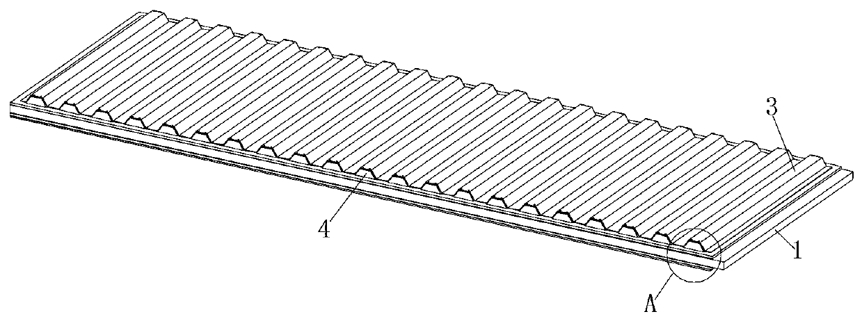
[0029] see Figure 1-2 , a forming process of a conveyor belt in the illustration, which specifically includes the following steps:

[0030] S1: Mixing of raw materials, mixing and processing of resin rubber and other raw materials;

[0031] S2: Parking, after the lower auxiliary machine of the internal mixer or the open mill completes the sheet production, the belt core 1 is formed, and sent to the warehouse for stacking, and stored for a period of time, and...


PUM

PropertyMeasurementUnit
thicknessaaaaaaaaaa

Abstract

The invention discloses a forming process of a conveyor belt. The forming process specifically comprises the following steps: S1, raw material mixing; S2, stopping; S3, mixed glue cooking; S4, calendaring; S5, strip billet cooling; S6, strip billet bottom cover glue attaching; S4, trapezoidal block attaching; S8, strip billet surface cover glue attaching; S9, conveyor belt forming; and S10, vulcanizing treatment. A plurality of trapezoidal blocks are additionally arranged at equal distance to increase a concave and convex feeling of a conveyor belt surface, so that a conveyor belt is not liable to slip while conveying goods; meanwhile, surface cover glue is in contact with the trapezoidal blocks, and is fixed with the trapezoidal blocks through bolts, so that corresponding bolts on damagedpositions can be unscrewed after local cover glue of the surface is damaged by rubbing, and cover glue on the damaged positions is cut off for adding and supplementing local cover glue while the whole conveyor belt does not need to replace, and therefore, financial resources are saved, and the service life of the conveyor belt is prolonged.

Description

technical field [0001] The invention relates to the technical field of conveyor belt production, in particular to a molding process of a conveyor belt. Background technique [0002] The conveyor belt is a belt installed on the conveyor to carry and convey materials. It consists of three parts, namely the belt core, the core rubber material and the cover rubber, which is the surface layer of the belt. The role of the cover rubber is mainly to protect the skeleton, transmit power and Conveying materials, resisting material wear, impact, corrosion, heat resistance, acid resistance, increasing traction and controlling materials to meet the function of conveying different substances. The traditional conveyor belt forming process route is to calender canvas and cover rubber on the calender respectively, and coil For standby, after laminating the calendered glued canvas on the forming machine according to the process requirements, the semi-finished belt embryo is made by laminating...

Claims


Application Information

Patent Timeline
Patent Type & Authority Applications(China)
IPC IPC(8): B29C43/24B29C43/58B29C65/48B29C35/02B29L29/00B29L31/00
CPCB29C35/02B29C43/245B29C43/58B29C65/48B29C2043/5808B29L2029/00B29L2031/7092
Inventor 林艳林承东
Owner 湖南宝烽设备股份有限公司
Why Eureka
Try Eureka