SVPWM modulation method, device and system
A modulation method and static coordinate system technology, applied in control systems, AC motor control, electrical components, etc., can solve problems such as unfavorable inverters to increase carrier frequency, low DC bus voltage utilization, multi-chip resources, etc., to achieve DC High voltage utilization, improve the overall effect, and improve the effect of carrier frequency
- Summary
- Abstract
- Description
- Claims
- Application Information
AI Technical Summary
Problems solved by technology
Method used
Image
Examples
Embodiment 1
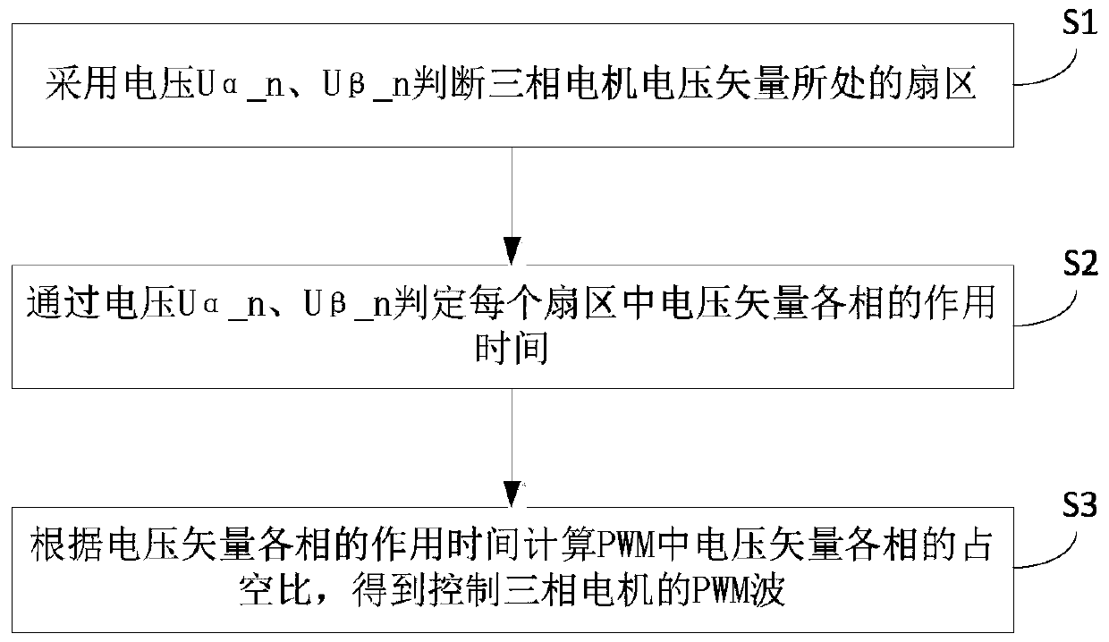
[0018] figure 1 It is the flow chart of the SVPWM modulation method in Embodiment 1, refer to figure 1 , the present embodiment proposes a SVPWM modulation method, which can be applied to the control of three-phase motors, so that the three-phase motors can obtain an ideal circular flux trajectory. The method can be executed by a SVPWM modulation device, which can be implemented in software. The device can be configured in an electronic device, such as a motor controller, and the method includes the steps of:
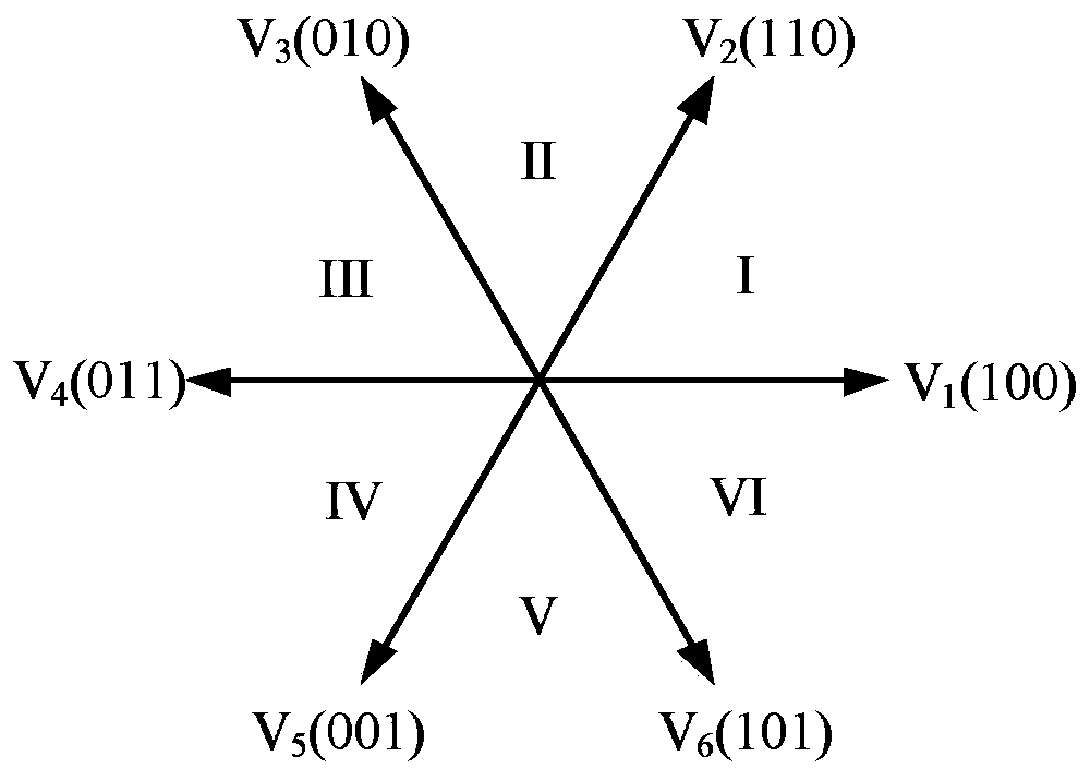
[0019] S1. Using voltage U α_n , U β_n Determine the sector where the voltage vector of the three-phase motor is located, in which the voltage U in the two-phase stationary coordinate system is affected by the bus voltage α , U β Perform per unitization to get the voltage U α_n , U β_n .
[0020] In this step, the formula used for per unitization is:
[0021]
[0022] Among them, U dc is the bus voltage.
[0023] In this step, the voltage U can be derived f...
Embodiment 2
[0077] image 3 It is the structural diagram of the SVPWM modulation device in the second embodiment, refer to image 3 , the present embodiment proposes a SVPWM modulation device, including a sector judging module 1 for adopting the voltage U α_n , U β_n Determine the sector where the voltage vector of the three-phase motor is located, in which the voltage U in the two-phase stationary coordinate system is affected by the bus voltage α , U β Perform per unitization to get the voltage U α_n , U β_n . Time calculation module 2: for passing voltage U α_n , U β_n , to determine the action time of each phase of the voltage vector in each sector. PWM module: Calculate the duty cycle of each phase of the voltage vector in PWM according to the action time of each phase of the voltage vector, and obtain the PWM wave for controlling the three-phase motor.
[0078] Specifically, the time calculation module 2 is also used to: set the maximum time threshold and the minimum time t...
Embodiment 3
[0082] Figure 4 It is the structural diagram of the SVPWM modulation system in the third embodiment, refer to Figure 4, this embodiment proposes a SVPWM modulation system, including a SVPWM modulation device 100, the SVPWM modulation device 100 can execute any SVPWM modulation method provided in Embodiment 1 of the present invention, and also includes a DC power supply 200, an inverter circuit 300 and a three-phase motor 400, the DC power supply 200 supplies power to the three-phase motor 400 through the inverter circuit 300, and the SVPWM modulation device 100 is used to generate PWM waves for controlling the three-phase motor.
[0083] Figure 5 It is another SVPWM modulation system structure diagram in Embodiment 3, refer to Figure 5 , optionally, the modulation system further includes an ADC sampling device 500, the ADC sampling device 500 is used to collect the current information of the three-phase motor 400, and convert the current information into the voltage U in...
PUM
 Abstract
Description
Claims
Application Information
 - Generate Ideas
- Intellectual Property
- Life Sciences
- Materials
- Tech Scout
- Unparalleled Data Quality
- Higher Quality Content
- 60% Fewer Hallucinations
Browse by: Latest US Patents, China's latest patents, Technical Efficacy Thesaurus, Application Domain, Technology Topic, Popular Technical Reports.
© 2025 PatSnap. All rights reserved.Legal|Privacy policy|Modern Slavery Act Transparency Statement|Sitemap|About US| Contact US: help@patsnap.com


