
Low-temperature negative-pressure wastewater zero-discharge system

A low-temperature negative pressure, zero-emission technology, applied in the direction of gaseous effluent wastewater treatment, multi-stage water treatment, water/sewage treatment, etc., can solve the problems of high-quality heat energy consumption and high energy consumption, reduce abrasion and improve heat transfer Effect, effect of extending heat usage

Pending Publication Date: 2020-02-04
CHINA HUADIAN ENG +1
View PDF0 Cites 1 Cited by
  • Summary
  • Abstract
  • Description
  • Claims
  • Application Information

AI Technical Summary

Problems solved by technology

[0005] Therefore, the technical problem to be solved by the present invention is to overcome the defects of high-quality heat energy consumption and high energy consumption in the existing desulfurization wastewater concentration technology, so as to provide a zero-discharge system for low-temperature negative-pressure wastewater

Method used


Image

  • Low-temperature negative-pressure wastewater zero-discharge system
  • Low-temperature negative-pressure wastewater zero-discharge system
  • Low-temperature negative-pressure wastewater zero-discharge system

Examples


Embodiment 1

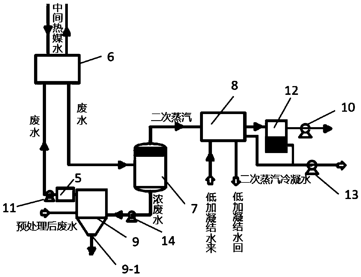
[0074] This embodiment provides a low-temperature negative pressure wastewater zero discharge system, such as figure 1 As shown, it includes a dust removal unit 1 and a desulfurization unit 2 connected together, and also includes an economizer 3 and a wastewater concentration system. The economizer 3 is arranged between the dust removal unit 1 and the desulfurization unit 2, or is arranged along the direction of flue gas flow. Before dust removal unit 1; dust removal unit 1 is an electric dust collector, desulfurization unit 2 is a desulfurization tower, and economizer 3 is a low-temperature economizer. The setting of economizer 3 can improve the dust removal capacity of dust removal unit 1.

[0075] Such as figure 2 As shown, the waste water concentration system includes: a first heat exchanger 6, which communicates with the economizer 3, so that the waste water and the first heat exchange medium from the economizer 3 exchange heat in the first heat exchanger 6; the first T...

Embodiment 2

[0101] Such as figure 1 As shown, this embodiment provides a zero-discharge system for low-temperature negative-pressure wastewater, which includes a connected dust removal unit 1, a desulfurization unit 2, and a chimney 4, and also includes an economizer 3 and a wastewater concentration system. The economizer 3 is installed in the dust removal Between unit 1 and desulfurization unit 2; dedusting unit 1 is an electric precipitator, desulfurization unit 2 is a desulfurization tower, and economizer 3 is a low-temperature economizer; figure 2 As shown, the waste water concentration system includes: a first heat exchanger 6, which communicates with the economizer 3, so that the waste water and the first heat exchange medium from the economizer 3 exchange heat in the first heat exchanger 6;

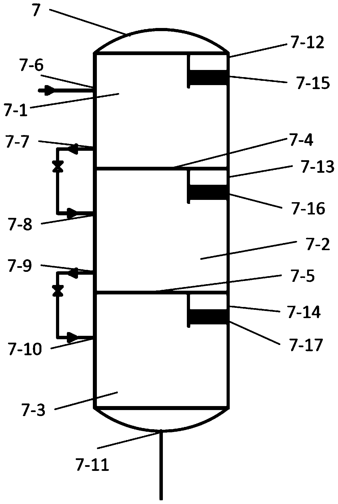
[0102] Flash tank 7, such as Figure 4 As shown, a first partition 7-4 and a second partition 7-5 are arranged inside, along the direction from the liquid inlet 7-6 of the flash tank 7 to th...

Embodiment 3

[0123] This embodiment provides a zero-discharge system for low-temperature negative-pressure wastewater, which is the same as Embodiment 2, the only difference is that the heat exchange component 8 in this embodiment is composed of a shell-and-tube heat exchanger, such as Figure 9 As shown, its specific structure is as follows:

[0124] The heat exchange assembly 8 includes a shell and a number of heat exchange tubes 8-10 arranged in it to form a shell side and a tube side respectively. The heating system is connected so that the second heat exchange medium in the low heating system enters the tube side to exchange heat with the steam in the shell side; the heat exchange assembly 8 is provided with a first baffle plate 8-11 and a second baffle plate 8-12 , along the direction of the outflow end and inflow end of the heat exchange tube 8-10, the first baffle plate 8-11 and the second baffle plate 8-12 are sequentially arranged in the heat exchange assembly 8 and divide the sh...


PUM


Abstract

The invention provides a low-temperature negative-pressure wastewater zero-discharge system. Flue gas is subjected to heat exchange with a first heat exchange medium after passing through a coal economizer, and a flash tank realizes multistage flash evaporation by utilizing gradient vacuum, so that concentration of desulfurized wastewater is facilitated; meanwhile, steam with different temperatures can be formed through multistage flash evaporation, and the steam enters a heat exchange assembly and is subjected to cascade heat exchange with a second heat exchange medium, so that the heat exchange effect is improved; through arrangement of a filter, desulfurized wastewater from a precipitation device can be effectively filtered, scale formation of a first heat exchanger and abrasion of dustin the wastewater to the first heat exchanger are reduced, and thus the heat exchange effect of the first heat exchanger is enhanced, and the service life of the first heat exchanger is prolonged; and after waste heat of flue gas increases the temperature of the wastewater, the flue gas precipitates in flash evaporation of the wastewater, and the waste heat of the flue gas is brought out along with steam, then is recovered by the second heat exchange medium, and finally returns to a low addition system. Under a condition that waste heat of the flue gas is almost not lost, cascade utilizationof heat energy is realized, the defect that high-quality heat energy is consumed in a conventional route is overcome, and energy consumption of units is reduced.

Description

technical field [0001] The invention relates to the technical field of environmental protection, in particular to a zero-discharge system for low-temperature negative-pressure wastewater. Background technique [0002] China's power energy is dominated by coal resources. With the increase of thermal power installed capacity, sulfur dioxide has become the main source of air pollution. Flue gas desulfurization (FGD) is the main process of industrial desulfurization. Among them, the wet limestone washing process has become the most common flue gas desulfurization technology because of its high desulfurization efficiency, good adaptability to coal types, mature process and reliable operation. However, desulfurization wastewater will be produced during the desulfurization process. The water quality and quantity characteristics of desulfurization wastewater are related to many factors such as unit load, coal composition, operating conditions, desulfurization process water quality, ...

Claims


Application Information

Patent Timeline
Patent Type & Authority Applications(China)
IPC IPC(8): C02F9/10C02F1/06C02F1/16F28D21/00C02F103/18
CPCC02F9/00C02F1/06C02F1/16F28D21/0001C02F1/043C02F1/042C02F2301/08C02F2303/10C02F2103/18C02F2001/007C02F1/001
Inventor 王争荣汪洋苏军划胡小夫夏怀鹏耿宣李伟王桦
Owner CHINA HUADIAN ENG
Learn More