
Diverter valve with improved seal

a diverter valve and seal technology, applied in the direction of conveying devices, mechanical equipment, transportation and packaging, etc., can solve the problems of affecting the sealing effect of the valve, the periphery of the valve gate structure is subject to abrasion, and the sealing is not tightly sealed, so as to reduce the wear and abrasion of the resilient component

Active Publication Date: 2007-11-06
SALINA VORTEX CONVEYOR
View PDF10 Cites 20 Cited by
  • Summary
  • Abstract
  • Description
  • Claims
  • Application Information

AI Technical Summary

Benefits of technology

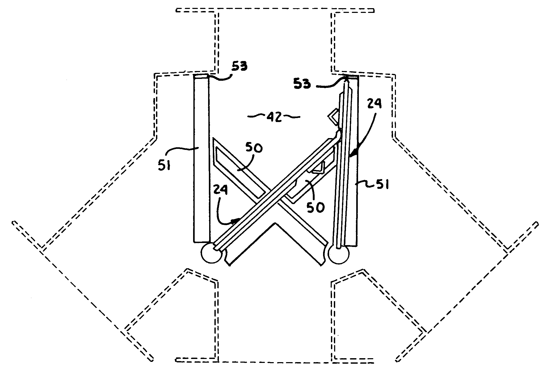
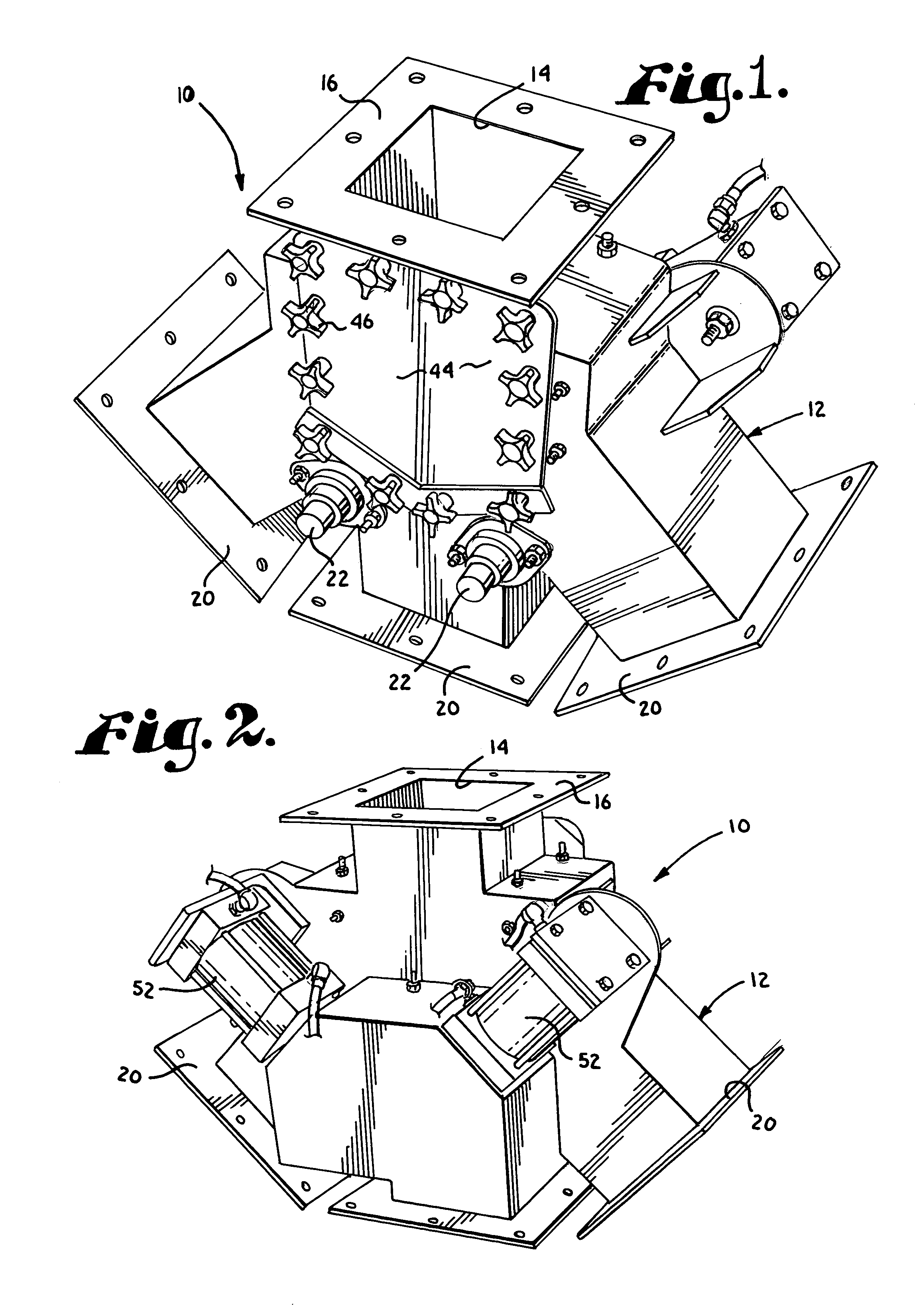
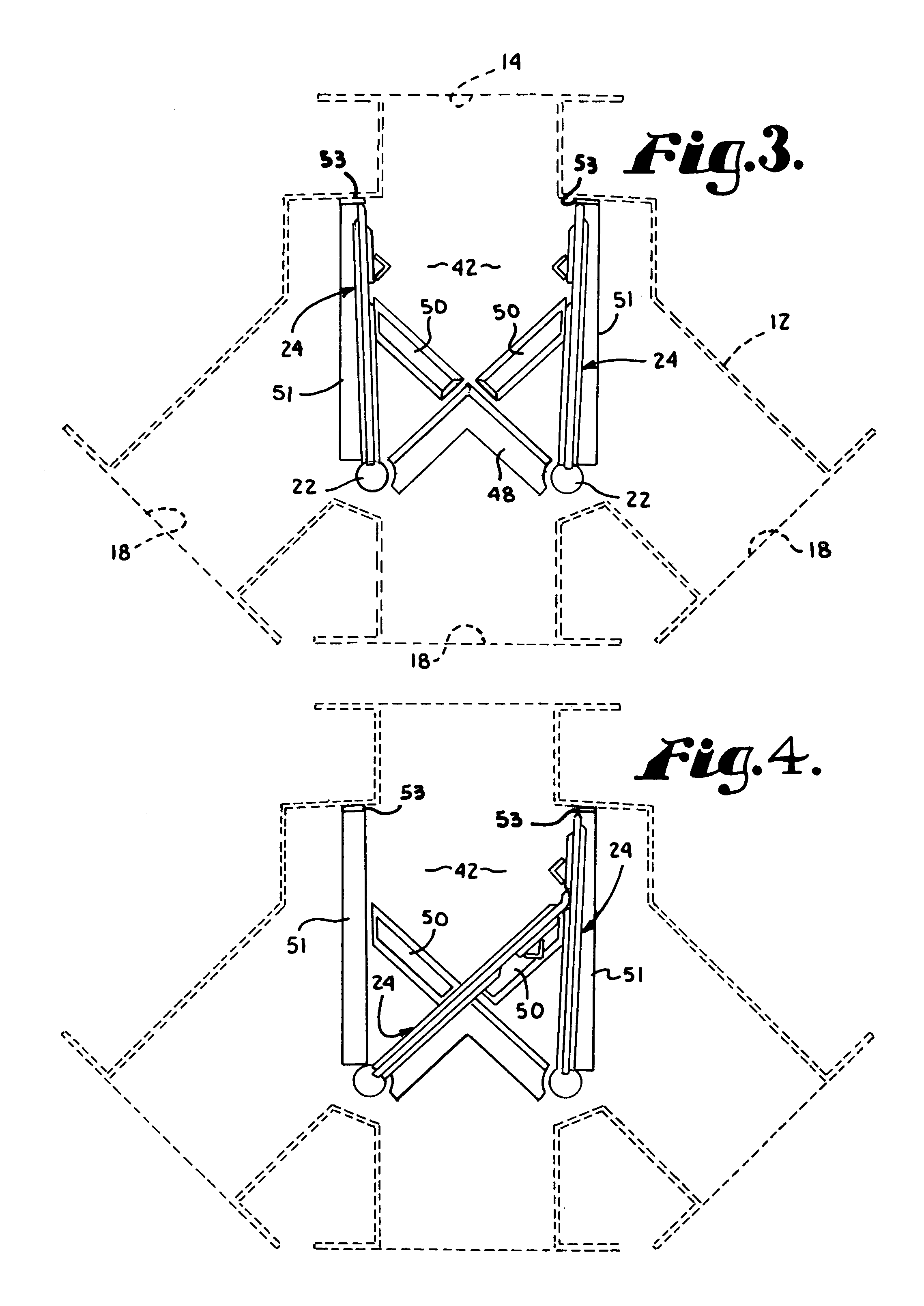
[0003]The present invention addresses the deficiencies of prior art diverter valves by providing a pivotal gate structure of a sandwich construction where two rigid planar lamina sandwich a planar resilient component between them so that the resilient material projects from the sides of the pivoting gate to provide a wiping seal that avoids metal on metal contact. One of the rigid lamina is also rigid with a moveable shaft. The other rigid lamina is formed in two sections with a gap between. When one pivoted gate is open, its resilient component rests in the aforementioned gap. A protective shield presented by the upper section of one rigid lamina greatly reduces wear and abrasion of the resilient component.
[0004]Thus, the invention encompasses a diverter valve for bulk solids which comprises a housing having an inlet and at least two outlets; gate structure comprising a resilient planar layer which extends around at least the periphery of a rigid planar component which is rigid with a shaft that is moved by a suitable prime mover. Preferably, the gate structure is constructed with two rigid planar lamina, one of which is formed in two sections so as to present a gap which receives the resilient structure of the second pivotal gate so as to protect it from abrasion by the material being handled.

Problems solved by technology

The problem that has heretofore been encountered, however, is that valves of this type do not seal tightly and some leakage of material occurs around the periphery of the valve gate structure.
Also, with traditional diverter gate valves, the leading edge of the gate structure is subject to abrasion from falling material since there is no structure to protect it.

Method used


Image

  • Diverter valve with improved seal
  • Diverter valve with improved seal
  • Diverter valve with improved seal

Examples


Embodiment Construction

[0012]Referring initially to FIG. 1 a diverter valve according to the present invention is designated generally by the number 10. Valve 10 comprises a housing 12 which presents a rectangular inlet 14 defined by a flange 16. Housing 12 also presents three separate rectangular outlets 18 (FIG. 3) surrounded by flanges 20.

[0013]Referring to FIG. 3, housing 12 mounts rotatable shafts 22 which support first and second gate structures 24. Since the two gate structures are of identical construction, only one will be described in detail. Referring to FIG. 6, gate structure 24 comprises a first rigid planar lamina 26 which is welded or otherwise rigidly secured to shaft 22 and a second rigid planar lamina 28 comprised of a generally rectangular first section 30 and a second section 32 which is spaced apart from the first section so as to present a gap 34. A resilient planar component 36 which is of a dimension greater than that of planar lamina 26 is sandwiched between layers 26 and 28. In t...


PUM


Abstract

A diverter valve for bulk solids is disclosed. The valve has a single inlet and two or more outlets, preferable three. Two pivotal gate valves are used for three outlets so that one is open and two are closed. The valve includes a novel pivotal gate structure which includes a resilient planar component sandwiched between two rigid planar components. The resilient component engages the valve housing so as to avoid metal to metal contact. The invention also includes a seal bar on each side of the housing which presents a linear surface that is perpendicular to the plane of the gate structure so as to present a firm surface against which the gate structure seals. The seal bars for each gate structure are discontinuous so as to accommodate positioning of the other gate structure in a smooth non-deformed sealing relationship to the housing. Additional seal bars engage the top and sides of each gate structure when moved to a “closed” position.

Description

BACKGROUND OF THE INVENTION[0001]This invention relates generally to valves for handling bulk solids and particularly to a pivotal gate valve of the type used in gravity flow applications to divert solid material from one pathway to another.[0002]One or more pivotal diverter valves are utilized in handling bulk solids to direct material between alternate pathways. The problem that has heretofore been encountered, however, is that valves of this type do not seal tightly and some leakage of material occurs around the periphery of the valve gate structure. Also, with traditional diverter gate valves, the leading edge of the gate structure is subject to abrasion from falling material since there is no structure to protect it.BRIEF SUMMARY OF THE INVENTION[0003]The present invention addresses the deficiencies of prior art diverter valves by providing a pivotal gate structure of a sandwich construction where two rigid planar lamina sandwich a planar resilient component between them so tha...

Claims


Application Information

Patent Timeline
Patent Type & Authority Patents(United States)
IPC IPC(8): F16K11/22
CPCF16K11/22F16K11/052Y10T137/87812
Inventor YOUNG, LEE EDWARDRYSER, JEFFREY LYNN
Owner SALINA VORTEX CONVEYOR
Learn More