
an injection molded structure

A cavity and bottom surface technology, applied in the field of injection molding structure, can solve the problems of great influence on product accuracy and quality, large deformation of injection molding cavity, small product structure size, etc., achieving low processing difficulty, ensuring continuity, and small impact. Effect

Active Publication Date: 2021-09-03
上海美翔实业有限公司
View PDF0 Cites 0 Cited by
  • Summary
  • Abstract
  • Description
  • Claims
  • Application Information

AI Technical Summary

Problems solved by technology

[0003] For products with internal compartments, the general solution is to directly process the injection cavity and glue position on the mold core, but the structure of this mold core is complex and the processing cost is very high, especially the structure size of the product is small, the injection molding process The degree of deformation of the middle injection molding cavity is relatively large, which has a great impact on the accuracy and quality of the product, especially the high frequency of repairs during the production process, which will easily lead to an increase in production costs and an extension of the delivery cycle

Method used


Image

  • an injection molded structure
  • an injection molded structure
  • an injection molded structure

Examples


Embodiment Construction

[0049] The present invention will be described in further detail below in conjunction with the accompanying drawings.

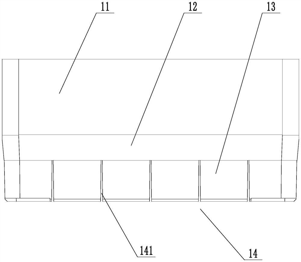
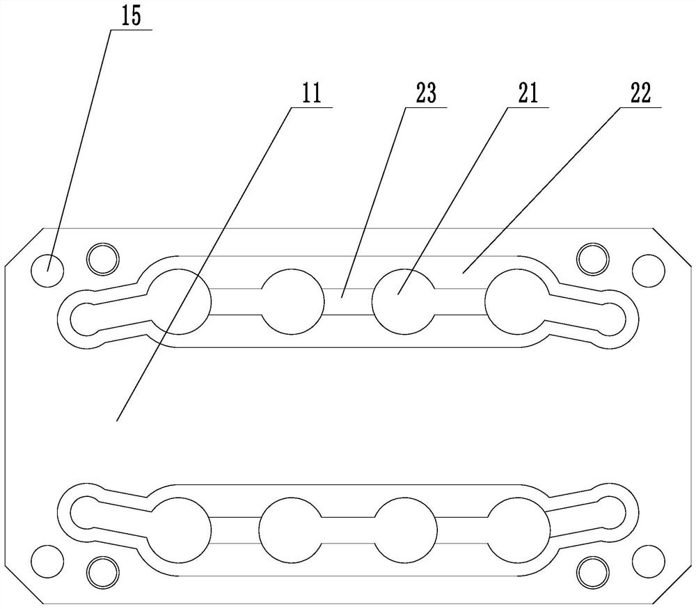
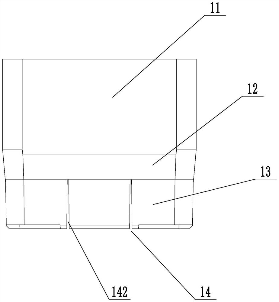
[0050] refer to figure 1 , is an injection molding structure disclosed in the embodiment of the present invention. The injection molding structure is used for the production of injection molded parts. Its main body is composed of a total of three parts: the first part 11, the second part 12 and the third part 13, wherein the first part 11 and The third part 13 is respectively fixed on the top surface and the bottom surface of the second part 12. For the sake of clarity of description, it is stipulated that the third part 13 is below, the second part 12 is in the middle, and the first part 11 is above, that is, the third part 13 is at the bottom. A part 11, a second part 12 and a third part 13 are arranged sequentially from top to bottom.

[0051] The first part 11 , the second part 12 and the third part 13 are integrally formed, that is, the three parts are ...


PUM


Abstract

The invention relates to an injection molding structure, which comprises a first part, a second part and a third part which are sequentially connected, the first part and the third part are respectively fixed on a set of mutually parallel sides of the second part, and the The sides are beveled. There is a mold cavity in the third part, including the first cavity and the second cavity; the bottom surfaces of the first cavity and the second cavity are connected with the bottom surface of the third part, and both of them are connected with the adjacent third part connected sideways. The positioning holes sequentially pass through the first part, the second part and the third part for fixing them on the mold. The first part is provided with a positioning blind hole, the upper end of which communicates with the top surface of the first part, and the lower end extends into the third part after passing through the second part. The invention is used for being installed on an injection mold for injection molding production, and can reduce the processing difficulty of products with compartments inside.

Description

technical field [0001] The invention relates to the technical field of injection molds, in particular to an injection molding structure. Background technique [0002] Injection mold is a tool for producing plastic products; it is also a tool for giving plastic products complete structure and precise dimensions. Injection molding is a processing method used in the mass production of certain complex-shaped parts. Specifically, it refers to injecting the heated and melted plastic into the mold cavity under high pressure from the injection molding machine, and after cooling and solidifying, a molded product is obtained. [0003] For products with internal compartments, the general solution is to directly process the injection cavity and glue position on the mold core, but the structure of this mold core is complex and the processing cost is very high, especially the structure size of the product is small, the injection molding process The degree of deformation of the middle in...

Claims


Application Information

Patent Timeline
Patent Type & Authority Patents(China)
IPC IPC(8): B29C45/26B29C45/36
CPCB29C45/2602B29C45/36B29C2045/363
Inventor 詹红军
Owner 上海美翔实业有限公司
Learn More