Dual-wavelength solder mask device
A dual-wavelength, solder mask technology, applied in the field of PCB manufacturing, can solve problems such as uneven illumination and uneven exposure of solder mask ink
- Summary
- Abstract
- Description
- Claims
- Application Information
AI Technical Summary
Problems solved by technology
Method used
Image
Examples
Embodiment 1
[0060] Embodiment 1. Vibrating motor type speckle dissipation structure
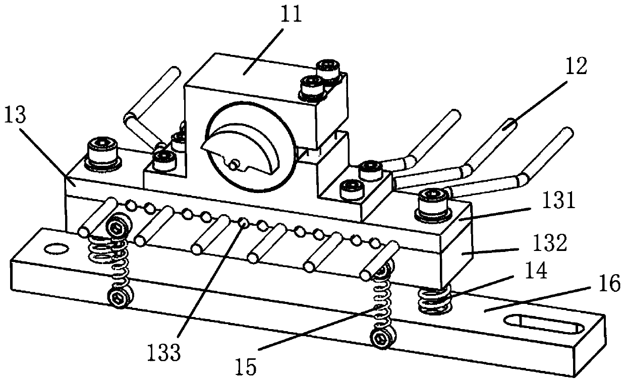
[0061] The vibration motor speckle dissipation structure of the illustrated embodiment includes: a vibration motor 11 , a multimode optical fiber 12 , an optical fiber clamping mechanism 13 , a damping spring and a fixing seat 1616 .
[0062] The vibration motor 11 is used as a vibration source. The vibration motor can adopt any existing vibration motor, as long as it can realize vibration. In one embodiment, the vibration motor has an eccentric wheel, and when the eccentric wheel rotates, it drives the entire motor to vibrate in the front-back and up-down directions. The frequency of vibration is achieved by adjusting or selecting the rotational speed of the vibration motor. Advantageously, the vibration motor 11 is an electric motor. During the entire working process of the dual-wavelength anti-soldering equipment, the vibration motor is operated to drive the multimode optical fiber 12 to always be ...
Embodiment 2
[0076] Embodiment 2. Linear Motion Dissipated Speckle Structure
[0077] The linear motion speckle dissipation structure of the embodiment shown in the figure includes: a driving motor 21 , a multimode optical fiber 22 , an optical fiber clamping mechanism 23 , a screw movement module, a fixing seat 26 and an origin sensor 27 .
[0078] The screw movement module includes a screw 24 and a linear slider 25 , and the linear slider 25 is provided with an internal thread matched with the screw 24 .
[0079] The driving motor 21 is installed on the fixing seat 26, and the screw rod 24 is driven to rotate forward and reverse repeatedly through the repeated forward and reverse rotation of the driving motor, and then the linear slider 25 is driven to reciprocate linearly along the axial direction of the screw rod 24 sports.
[0080] The multimode fiber 22 is the same as that of the first embodiment.
[0081] The optical fiber clamping mechanism 23 is basically the same in structure a...
Embodiment 3
[0086] Embodiment 3. Cam motion type speckle dissipation structure
[0087] The illustrated cam-type speckle dissipation structure includes: a driving motor 31 , a multimode optical fiber 32 , an optical fiber clamping mechanism 33 , a cam 34 , a linear slider 35 , a fixing seat 36 and a tension spring 37 .
[0088] working principle:
[0089] When the cam 34 is rotated by the driving motor 31, it drives the linear slider 35 to move linearly, so that the optical fiber clamping mechanism 33 and the multimode optical fiber 32 move together. The interior of the multimode fiber 32 moves forward and backward following the high and low points, thereby changing the position of the reflection point in the middle of the multimode fiber 32 , thereby changing the reflection point of the light beam inside the multimode fiber 32 . The cam 34 drives the linear slider 35 through contact transmission with two rollers.
[0090] The pull-back spring 37 ensures that when the cam 34 transitions...
PUM
 Abstract
Description
Claims
Application Information
 - Generate Ideas
- Intellectual Property
- Life Sciences
- Materials
- Tech Scout
- Unparalleled Data Quality
- Higher Quality Content
- 60% Fewer Hallucinations
Browse by: Latest US Patents, China's latest patents, Technical Efficacy Thesaurus, Application Domain, Technology Topic, Popular Technical Reports.
© 2025 PatSnap. All rights reserved.Legal|Privacy policy|Modern Slavery Act Transparency Statement|Sitemap|About US| Contact US: help@patsnap.com


