
A high-frequency high-power microwave device

A high-power microwave and high-frequency technology is applied in the direction of the circuit components of the time-of-flight electron tube and the coupling device of the time-of-flight electron tube. It can solve the problems of reducing the radial size and power capacity, and achieve the axial And the effect of compact radial size, light weight and simple structure size

Active Publication Date: 2021-10-26
INST OF APPLIED ELECTRONICS CHINA ACAD OF ENG PHYSICS
View PDF10 Cites 0 Cited by
  • Summary
  • Abstract
  • Description
  • Claims
  • Application Information

AI Technical Summary

Problems solved by technology

The increase in device frequency drastically reduces the radial size of the device, resulting in a reduction in power capacity

Method used


Image

  • A high-frequency high-power microwave device

Examples


Embodiment 1

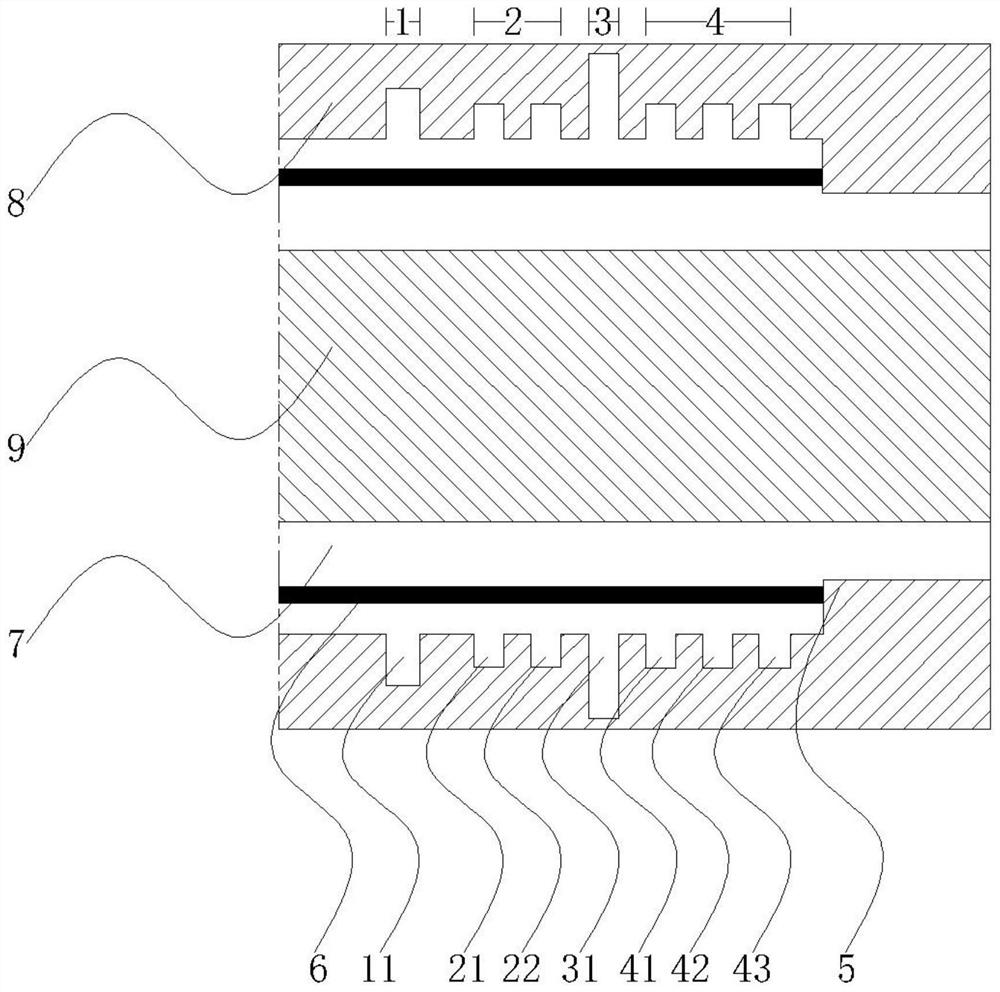
[0028] Such as figure 1 As shown, a high-frequency high-power microwave device in this embodiment includes a circular waveguide sleeve and an inner conductor coaxial with the circular waveguide sleeve. One end of the circular waveguide sleeve is provided with a cathode emitting an annular electron beam. The inner diameter of the circular waveguide sleeve is 14.6 mm, and the diameter of the inner conductor is 8 mm.

[0029] The coaxial reflection area, beam pre-modulation area, phase modulation area and beam conversion area are arranged in sequence along the electron beam transmission direction; the reflection area, beam pre-modulation area, phase modulation area and beam conversion area are respectively arranged in the An annular groove-shaped reflective cavity with a rectangular section, a beam pre-modulation cavity, a phase modulation cavity and a beam conversion cavity are arranged on the top.

[0030] The outer diameter of the reflective cavity in the reflective area is 1...


PUM

PropertyMeasurementUnit
diameteraaaaaaaaaa
lengthaaaaaaaaaa
diameteraaaaaaaaaa

Abstract

The invention discloses a high-frequency and high-power microwave device, which comprises a circular waveguide sleeve and an inner conductor coaxial with the circular waveguide sleeve. An electronic device with an inner diameter of 8mm and an outer diameter of 14.6mm is formed between the inner conductor and the circular waveguide sleeve. Beam transmission channel; the high-frequency structure is provided with a coaxial reflection area, a beam pre-modulation area, a phase modulation area and a beam conversion area in sequence along the electron beam transmission direction; after the beam conversion area, a radially inwardly protruding annular collector is set ;Reflective area, beam pre-modulation area, phase modulation area and beam conversion area, respectively set annular groove-shaped reflection cavity, beam pre-modulation cavity, phase modulation cavity and beam conversion cavity on the circular waveguide sleeve; inner diameter 12mm , an outer diameter of 12.6mm, a voltage of 400kV, and a beam intensity of 7.3kA are transmitted in a high-frequency structure under the guidance of an axial magnetic field with a magnetic field strength of 1.5T, generating high-frequency and high-power microwaves with a frequency of 67.4GHz. The high-frequency and high-power microwave device of the present invention has the advantages of simple structure size, miniaturization, light weight and easy assembly.

Description

technical field [0001] The invention relates to a high-frequency and high-power microwave device, belonging to the technical field of high-power microwave devices. Background technique [0002] High-power microwave generally refers to electromagnetic waves with peak power above 100MW and operating frequency in the range of 1-300GHz. With the research and application requirements of high-power microwave technology, high-power microwave sources are gradually developing to high-frequency structures. [0003] The axial O-shaped high-power microwave device is a kind of high-power microwave device that is widely used due to the easy guidance of the electron beam brought by the structure and the variable combination of the structure. The increase in device frequency drastically reduces the radial size of the device, thereby causing a reduction in power capacity. This physical mechanism is a key problem that must be solved for high-frequency and high-power microwave devices. In t...

Claims


Application Information

Patent Timeline
Patent Type & Authority Patents(China)
IPC IPC(8): H01J23/36H01J23/16
CPCH01J23/16H01J23/36
Inventor 丁恩燕张运俭
Owner INST OF APPLIED ELECTRONICS CHINA ACAD OF ENG PHYSICS
Learn More