Cutting type series-connection multi-stage pressure-reduction regulating valve

A decompression regulating valve, grooved technology, applied in the field of regulating valves, can solve the problems of short service life, serious erosion of sealing surface, poor sealing performance, etc., to achieve the effect of reducing erosion damage, prolonging service life and reducing impact

Inactive Publication Date: 2020-01-21
TIANXING FIRE FIGHTING EQUIP GRP CO LTD
View PDF9 Cites 0 Cited by
  • Summary
  • Abstract
  • Description
  • Claims
  • Application Information

AI Technical Summary

Problems solved by technology

For the high pressure difference working conditions of gas, liquid, steam, solid-containing liquid and other media, the single-seat plunger type control valve or the traditional single-stage sleeve type control valve commonly used at present has the disadvantage of short service life
[0003] In the existing technical solution, the application number is 201811146239.4, a grooved series series multi-stage pressure reducing regulating valve, which includes a valve body and a valve cover; the valve body is provided with a valve inlet and a valve outlet, and the valve body and valve The cavity surrounded by the cover is provided with a valve seat, a grooved valve core capable of axial movement and an energy dissipation chamber; the valve seat is arranged on the top of the valve inlet, and the energy dissipation chamber is airtightly pressed against the valve seat and the valve cover Between, the energy dissipation chamber is provided with a diversion hole at the end close to the valve cover to connect the energy dissipation chamber and the valve outlet; Cooperate with sliding joints to form multi-stage decompression and throttling units in series; the grooved valve core is provided with a plurality of decompression grooves corresponding to the multi-stage ribs in the axial direction; the grooved valve core is in different Under the opening degree, the medium has the following three overcurrent states: when the opening degree is zero, the grooved valve core and the valve seat fit together to form a sealing pair to cut off the flow of the medium; or when the opening degree is small, the grooved valve core is separated from the valve seat At the same time, the adjacent decompression and throttling unit is not connected through the decompression groove and the medium is in the gap flow state; or when the opening is large, the grooved valve core is out of contact with the valve seat, and at the same time the adjacent decompression section The flow unit is connected through the decompression groove, and the medium is in an adjustable flow state; however, this technical solution still has the following problems: under the condition of solid medium, the high-speed medium flow will scour the sealing surface of the grooved valve core when the opening is small. Seriously, it is easy to cause the sealing surface to rush out of the streamlined groove, resulting in poor sealing after the sealing surface has been used for a period of time, and the service life of the grooved valve core is short; so it is necessary to solve these problems

Method used


Image

  • Cutting type series-connection multi-stage pressure-reduction regulating valve
  • Cutting type series-connection multi-stage pressure-reduction regulating valve
  • Cutting type series-connection multi-stage pressure-reduction regulating valve

Examples


Embodiment Construction

[0030] The principles and features of the present invention are described below in conjunction with the accompanying drawings, and the examples given are only used to explain the present invention, and are not intended to limit the scope of the present invention.

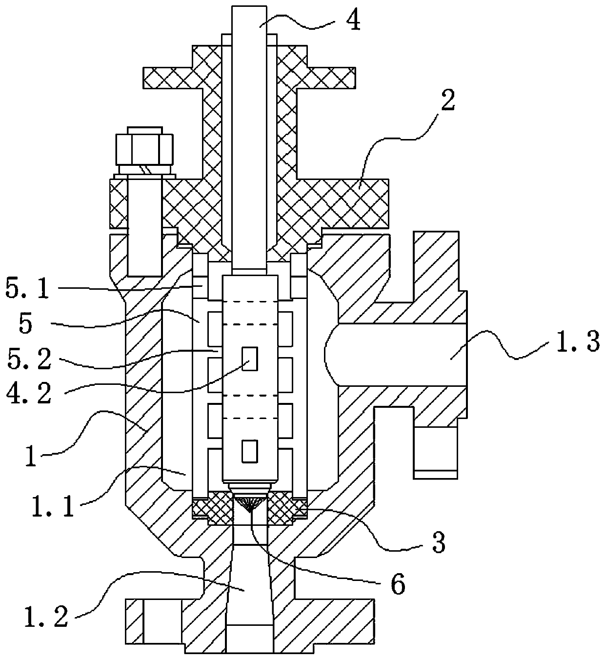
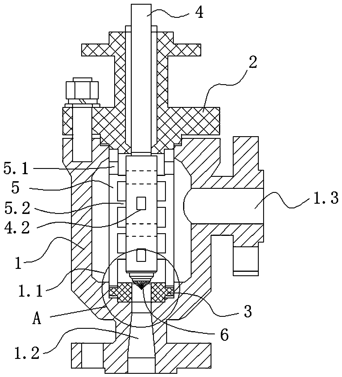
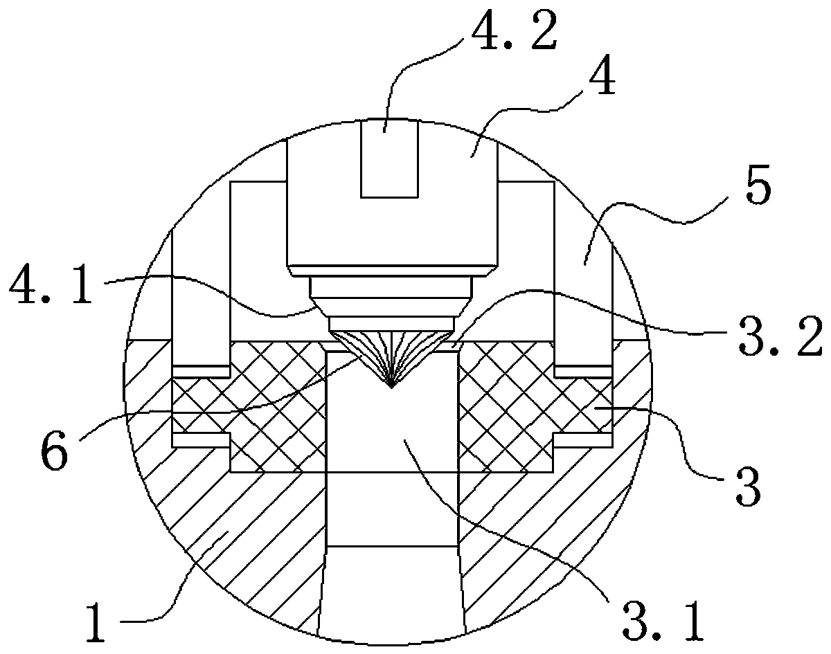
[0031] Such as Figure 1 to Figure 4 As shown, a slotted series series multi-stage pressure reducing regulating valve includes a valve body 1 and a valve cover 2, the valve body 1 is provided with a cavity 1.1, and the valve cover 2 is placed on the valve body 1 The upper end is detachably connected with the valve body 1; the valve body 1 is provided with a valve inlet 1.2 and a valve outlet 1.3 communicating with the cavity 1.1; the cavity 1.1 is provided with a valve seat 3, which can Axially moving valve core 4 and energy dissipation chamber 5; the valve seat 3 is placed on the top of the valve inlet 1.2, and the energy dissipation chamber 5 is airtightly pressed between the valve seat 3 and the valve cover 2. T...


PUM


Abstract

The invention relates to a cutting type series-connection multi-stage pressure-reduction regulating valve which comprises a valve body and a valve deck. A cavity is formed in the valve body. The valvedeck is placed at the upper end of the valve body and detachably connected with the valve body. A valve inlet and a valve outlet are formed in the valve body. A valve seat, a valve element and an energy dissipating chamber are arranged in the cavity. The valve seat is placed on the top of the valve inlet. The energy dissipating chamber is pressed between the valve seat and the valve deck in a sealed mode. The side wall of the upper end of the energy dissipating chamber is provided with a flow guide hole communicating with the energy dissipating chamber and the valve outlet. A multi-stage ribplate is arranged in the energy dissipating chamber. The upper portion of the valve element vertically upwards penetrates through the valve deck. The lower portion of the valve element vertically downwards penetrates through the energy dissipating chamber to be detachably connected with the valve seat. The lower end of the valve element is provided with a direction changing device for changing theflowing direction of a high-speed medium. The direction changing device is fixedly connected with the lower end of the valve element. The direction changing device can extend into the valve seat. Compared with the prior art, the corrosion damage to the sealed face of the valve element is reduced, the impact on the inner wall of the energy dissipating chamber is reduced, and the service life of the valve element and the energy dissipating chamber is prolonged.

Description

technical field [0001] The invention relates to the technical field of regulating valves, in particular to a slotted series series multi-stage pressure reducing regulating valve. Background technique [0002] Regulating valve is an important part of automatic control, and its adjustment accuracy and reliability will affect the safety and stability of automatic operation. For the high pressure difference working conditions of gas, liquid, steam, solid-containing liquid and other media, the single-seat plunger type control valve or the traditional single-stage sleeve type control valve commonly used at present has the disadvantage of short service life. [0003] In the existing technical solution, the application number is 201811146239.4, a grooved series series multi-stage pressure reducing regulating valve, which includes a valve body and a valve cover; the valve body is provided with a valve inlet and a valve outlet, and the valve body and valve The cavity surrounded by ...

Claims


Application Information

Patent Timeline
Patent Type & Authority Applications(China)
IPC IPC(8): F16K1/38F16K1/42F16K1/54F16K27/08F16K47/02F16K47/08
CPCF16K1/38F16K1/422F16K1/54F16K27/08F16K47/023F16K47/08
Inventor 郑海彬洪小燕
Owner TIANXING FIRE FIGHTING EQUIP GRP CO LTD
Why Eureka
Try Eureka