
Gear pump glue injecting head

A gear pump and glue injection head technology, which is applied in the direction of multi-way valves, engine components, and devices for coating liquid on the surface, etc., can solve the problem that the glue output rate is difficult to control, continuous glue injection cannot be satisfied, and the glue injection accuracy is not high. problems, achieve the effect of large glue output, reduce maintenance cost and prolong maintenance cycle

Pending Publication Date: 2020-01-21
JIANGSU YIKONG VACUUM INJECTION TECH CO LTD
View PDF0 Cites 0 Cited by
  • Summary
  • Abstract
  • Description
  • Claims
  • Application Information

AI Technical Summary

Problems solved by technology

[0004] The purpose of the present invention is to provide a gear pump glue injection head to solve the problem that the glue output ratio of the gear pump glue injection head on the market depends on hardware control, which cannot be adjusted quickly and randomly, and the glue output The speed is not easy to control, and the amount of single injection is limited by the height of the inner diameter of the cylinder liner. For large-volume production tasks, the comprehensive injection speed is slow and the work efficiency is low, which cannot meet continuous injection and the injection accuracy is not high. question

Method used


Image

  • Gear pump glue injecting head
  • Gear pump glue injecting head
  • Gear pump glue injecting head

Examples


Embodiment Construction

[0020] The following will clearly and completely describe the technical solutions in the embodiments of the present invention with reference to the accompanying drawings in the embodiments of the present invention. Obviously, the described embodiments are only some, not all, embodiments of the present invention. Based on the embodiments of the present invention, all other embodiments obtained by persons of ordinary skill in the art without making creative efforts belong to the protection scope of the present invention.

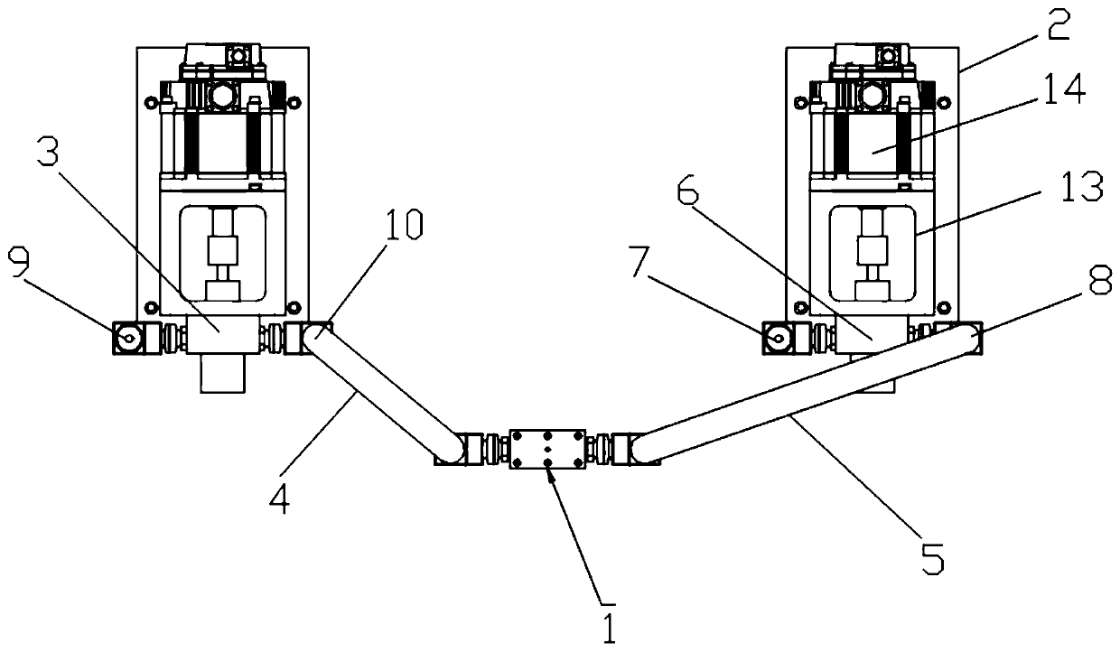
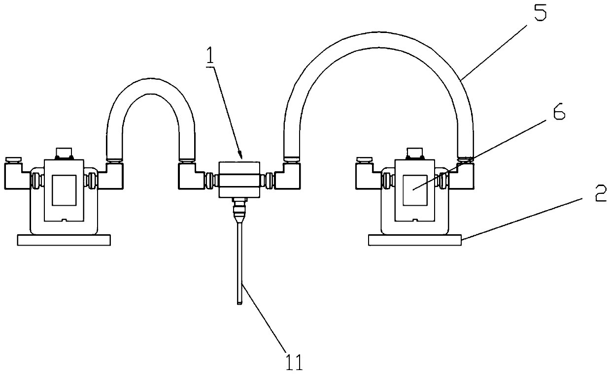
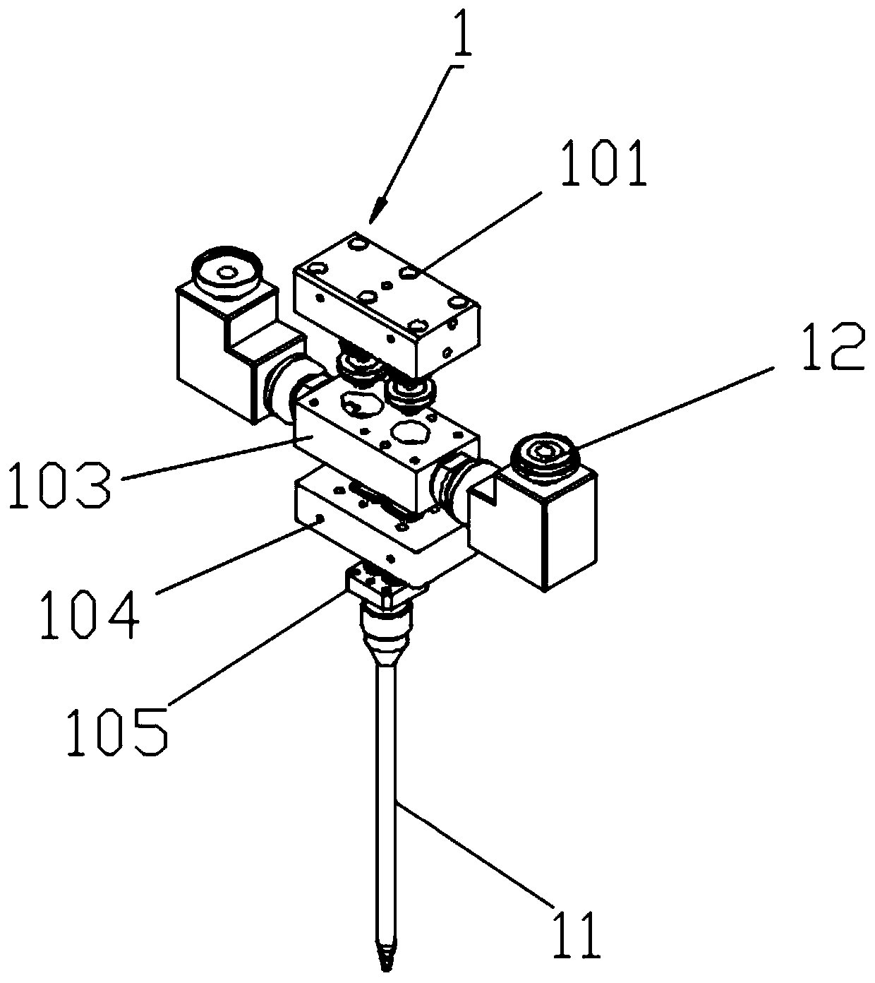
[0021] see Figure 1-5 , the present invention provides a technical solution: a gear pump glue injection head, including a switch valve 1, a switch valve block 101, a valve core 102, a valve bottom plate 103, a discharge plate 104, a glue nozzle 105, a load plate 2, a gear Pump one 3, feed pipe one 4, feed pipe two 5, gear pump two 6, feed inlet 1 7, feed outlet 1 8, feed inlet 2 9, feed outlet 2 10, static mixing pipe 11, feed pipe Connector 12, mounting bra...


PUM


Abstract

The invention discloses a gear pump glue injecting head. The gear pump glue injecting head comprises a switching valve and a bearing plate; a first material pipe and a second material pipe are symmetrically connected to the two ends of the switching valve; a mounting bracket is mounted on the upper end surface of the bearing plate; a servo motor is mounted on the upper end surface of the mountingbracket; a second gear pump is mounted on the bottom end surface of the mounting bracket; a first gear pump is mounted in the position, symmetrical to the switching valve, of the second gear pump; a first feed port is formed in the left end of the second gear pump; a first discharge port is formed in the right end of the second gear pump; a second feed port is formed in the left end of the first gear pump; and a second discharge port is formed in the right end of the first gear pump. The gear pump glue injecting head can control the glue outlet ratio and the glue outlet speed; through the gearpump metering mode, the effects of continuous glue discharging, high glue discharging quantity, stable glue discharging flow and precise metering can be achieved; the maintenance cost is reduced; theproduction efficiency is improved; the stable pressure in the first material pipe and the second material pipe can be maintained; and the accurate glue discharging precision is guaranteed.

Description

technical field [0001] The invention relates to the technical field of glue injection and glue pouring, in particular to a gear pump glue injection head. Background technique [0002] The gear pump glue injection head is a component used to pour glue into the product on the gear pump glue injection device. With the continuous development of science and technology, the structure and function of the gear pump glue injection head have been improved accordingly. The main application It has a good application prospect in technical fields such as building construction and interior decoration; [0003] The glue output ratio of the gear pump injection head on the market depends on hardware control, and the glue output ratio cannot be adjusted quickly and freely, and the glue output rate is not easy to control. The single injection amount is limited by the height of the inner diameter of the cylinder liner. At this time, the comprehensive glue injection speed is slow, the work effic...

Claims


Application Information

Patent Timeline
Patent Type & Authority Applications(China)
IPC IPC(8): B05C5/02B05C11/10F16K11/22
CPCB05C5/0229B05C11/1036F16K11/22
Inventor 施伟胡瑞瑞
Owner JIANGSU YIKONG VACUUM INJECTION TECH CO LTD
Learn More