Boiler fly ash after-combustion device and method
A fly ash reburning and boiler technology, which is applied in the boiler field to achieve the effects of reducing ammonia escape, reducing ammonia water consumption, and reducing original emissions
- Summary
- Abstract
- Description
- Claims
- Application Information
AI Technical Summary
Problems solved by technology
Method used
Image
Examples
Embodiment 1
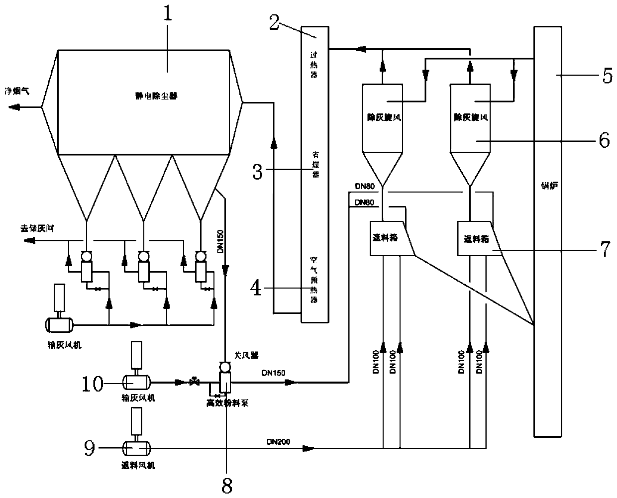
[0018] refer to figure 1 , a boiler fly ash recombustion device, comprising a boiler 5, the upper end of the boiler 5 communicates with a cyclone separator 7, the gas outlet end of the cyclone separator 7 is connected with the auxiliary heating surface of the boiler 5, and the auxiliary heating surface The lower end is connected with the electrostatic precipitator 1, the ash outlet of the electrostatic precipitator 1 is connected with the fly ash device, the fly ash device is connected with the ash storage room, and the fly ash device is also connected with the material of the return box. The legs are connected, the material legs of the return box are connected with the furnace of the boiler 5, and the lower end of the return device is connected with the return fan 9.
[0019] The auxiliary heating surface includes a superheater 2, an economizer 3 and an air preheater 4, and the superheater 2, the economizer 3 and the air preheater 4 are connected in sequence, wherein the supe...
Embodiment 2
[0023] refer to figure 1 , a boiler fly ash recombustion device, comprising a boiler 5, the upper end of the boiler 5 communicates with a cyclone separator 7, the gas outlet end of the cyclone separator 7 is connected with the auxiliary heating surface of the boiler 5, and the auxiliary heating surface The lower end is connected with the electrostatic precipitator 1, the ash outlet of the electrostatic precipitator 1 is connected with the fly ash device, the fly ash device is connected with the ash storage room, and the fly ash device is also connected with the material of the return box. The legs are connected, the material legs of the return box are connected with the furnace of the boiler 5, and the lower end of the return device is connected with the return fan 9.
[0024] The auxiliary heating surface includes a superheater 2, an economizer 3 and an air preheater 4, and the superheater 2, the economizer 3 and the air preheater 4 are connected in sequence, wherein the supe...
Embodiment 3
[0028] refer to figure 1 , a boiler fly ash recombustion device, comprising a boiler 5, the upper end of the boiler 5 communicates with a cyclone separator 7, the gas outlet end of the cyclone separator 7 is connected with the auxiliary heating surface of the boiler 5, and the auxiliary heating surface The lower end is connected with the electrostatic precipitator 1, the ash outlet of the electrostatic precipitator 1 is connected with the fly ash device, the fly ash device is connected with the ash storage room, and the fly ash device is also connected with the material of the return box. The legs are connected, the material legs of the return box are connected with the furnace of the boiler 5, and the lower end of the return device is connected with the return fan 9.
[0029] The auxiliary heating surface includes a superheater 2, an economizer 3 and an air preheater 4, and the superheater 2, the economizer 3 and the air preheater 4 are connected in sequence, wherein the supe...
PUM
 Abstract
Description
Claims
Application Information
 - R&D
- Intellectual Property
- Life Sciences
- Materials
- Tech Scout
- Unparalleled Data Quality
- Higher Quality Content
- 60% Fewer Hallucinations
Browse by: Latest US Patents, China's latest patents, Technical Efficacy Thesaurus, Application Domain, Technology Topic, Popular Technical Reports.
© 2025 PatSnap. All rights reserved.Legal|Privacy policy|Modern Slavery Act Transparency Statement|Sitemap|About US| Contact US: help@patsnap.com

