
Plated piston rod assembly polishing processing device and processing method thereof

A technology for processing equipment and piston rods, applied in metal processing equipment, grinding/polishing equipment, control of workpiece feed movement, etc., can solve problems such as low processing efficiency, long average workpiece time, long polishing and inspection time, etc. Achieve the effects of high processing efficiency, accelerated processing rhythm, and short walking stroke

Pending Publication Date: 2020-01-14
苏州迅益科系统科技有限公司
View PDF0 Cites 7 Cited by
  • Summary
  • Abstract
  • Description
  • Claims
  • Application Information

AI Technical Summary

Problems solved by technology

[0003] The existing polishing and testing production line of the piston rod assembly is a linear layout, that is, the cycle process of loading, polishing, testing, unloading and loading the next workpiece is sequentially carried out on the piston rod assembly. However, due to the long polishing and testing time, About 25-35 seconds per workpiece, resulting in long average working hours and low processing efficiency

Method used


Image

  • Plated piston rod assembly polishing processing device and processing method thereof
  • Plated piston rod assembly polishing processing device and processing method thereof
  • Plated piston rod assembly polishing processing device and processing method thereof

Examples


Embodiment Construction

[0059] The invention provides a polishing processing equipment and processing method of a piston rod assembly after plating, which polishes the surface of the piston rod assembly after chrome plating and detects the polishing effect.

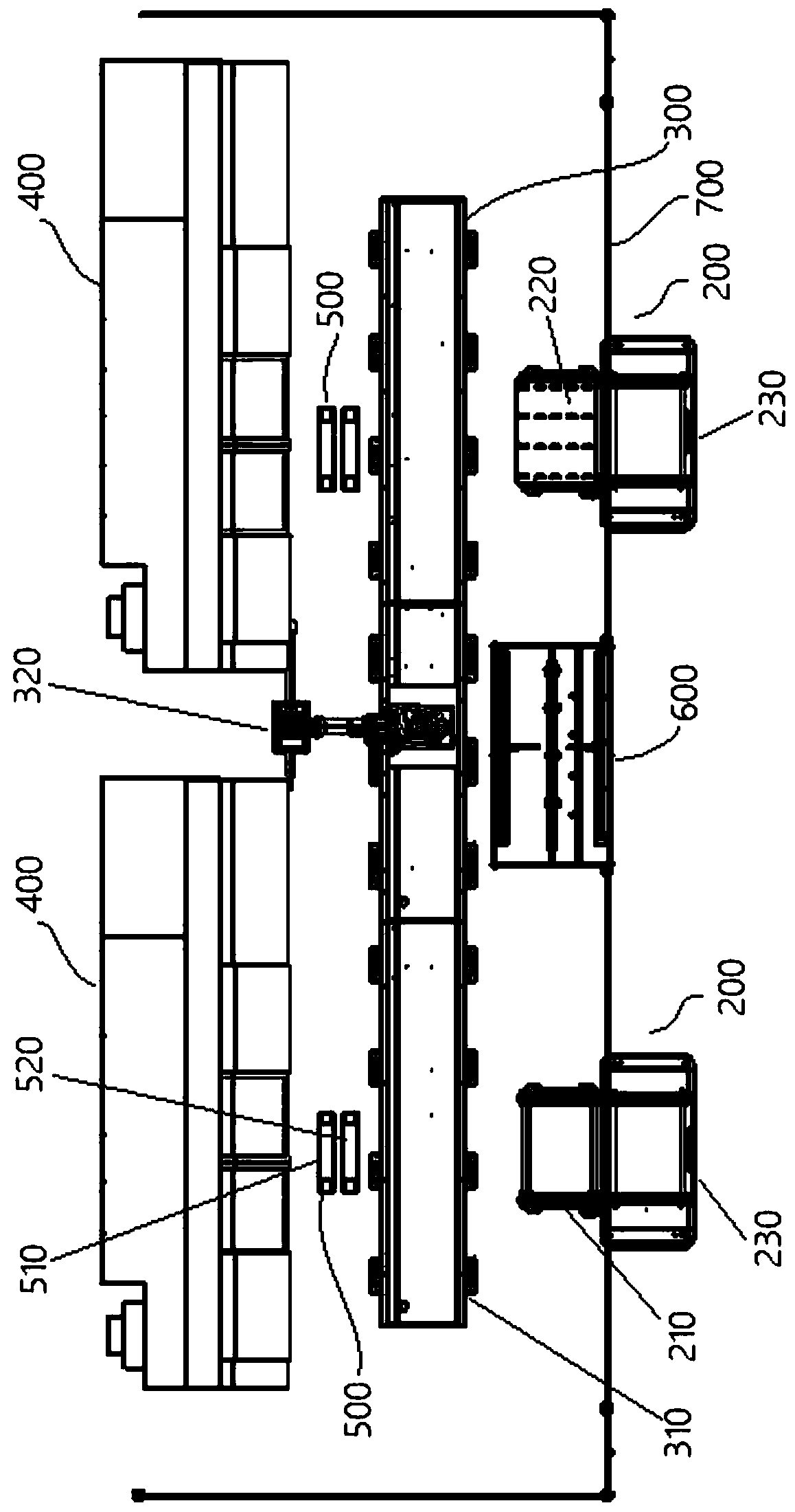
[0060] Such as figure 1 As shown, the equipment includes a loading and unloading buffer station 200 , a ground rail robot 300 , an outer cylindrical grinder 400 , a grinding machine buffer station 500 and a detection platform 600 .

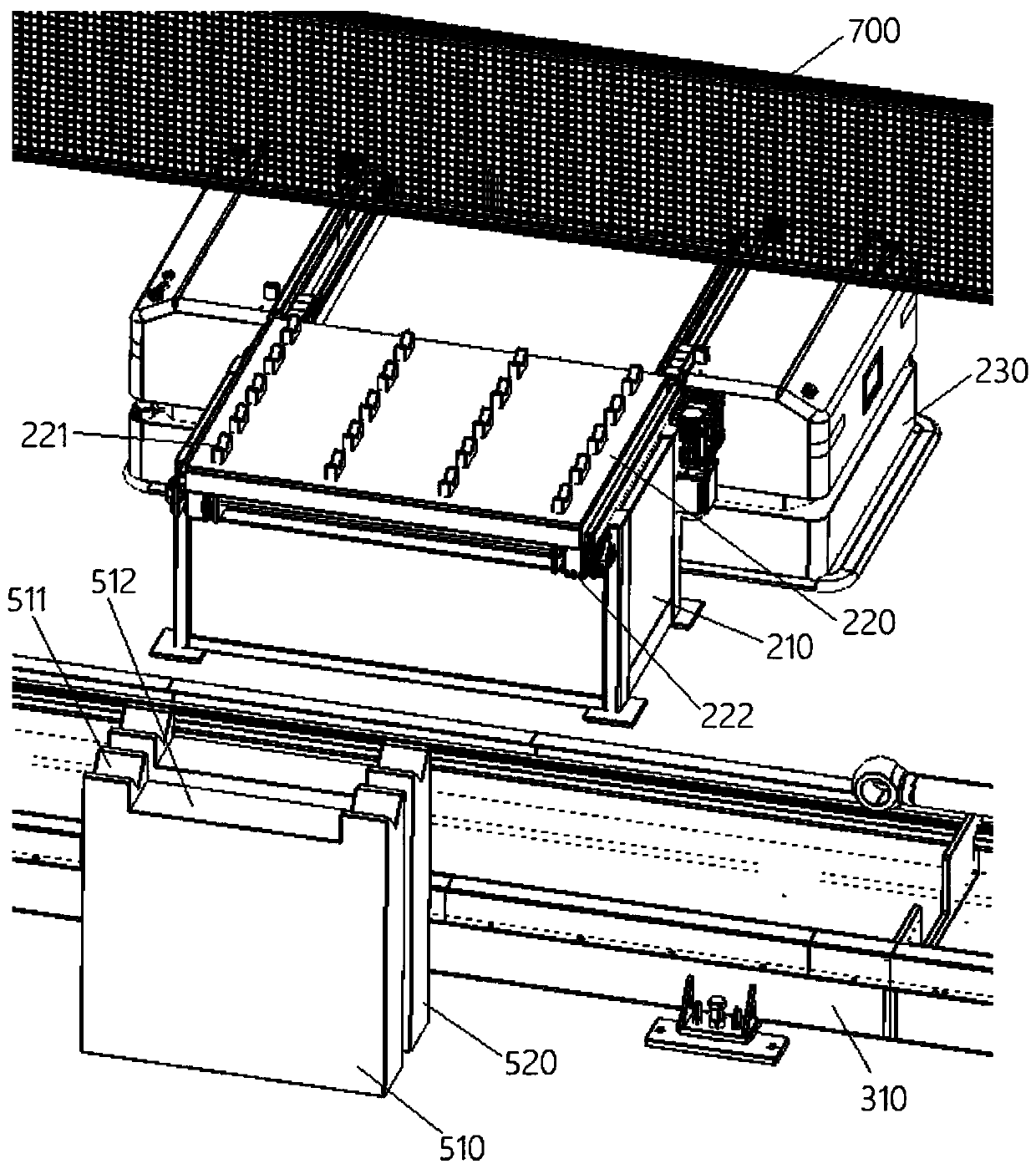
[0061] Such as figure 1 with figure 2 As shown, two loading and unloading buffer stations 200 are distributed on the front side of the ground rail robot 300 at intervals along the left and right directions. The loading and unloading cache station 200 includes a tray cache table 210 and a workpiece tray 220. The tray cache table 210 is fixed on the ground, and the workpiece tray 220 can be placed on the tray cache table 210; the workpiece tray 220 is used to store the workpiece to be polished. The piston rod asse...


PUM


Abstract

The inventin provides a plated piston rod assembly polishing processing device which comprises loading and unloading caching stations, a ground track robot, cylindrical grinding machines, grinding machine caching stations and a detection platform. The two loading and unloading caching stations are distributed on the front side of the ground track robot; workpiece trays are arranged on the loadingand unloading caching stations; multiple V-shaped support blocks are arranged on the workpiece trays and can position piston rod assemblies; a ground track of the ground track robot is arranged alongthe left-and-right direction; a manipulator can move along the ground track; the two cylindrical grinding machines are located on the back side of the ground track robot; the two grinding machine caching stations are located on the front sides of the two cylindrical grinding machines; a first workpiece support frame and a second workpiece support frame are arranged on the grinding machine cachingstations; the detection platform is located between the two loading and unloading caching stations; a detection scanner is arranged on the detection platform and can be used for detecting faults of the surfaces of the piston rod assemblies; the detection scanner is connected with a controller; and the controller is connected with the ground track robot. The plated piston rod assembly polishing processing device provided by the invention has high processing efficiency.

Description

technical field [0001] The invention belongs to the technical field of piston rod processing, and in particular relates to a polishing processing device and a processing method of a plated piston rod assembly. Background technique [0002] The processing process of the piston rod assembly includes welding the lifting ring on the piston rod body to form the piston rod assembly, and then chrome-plating and polishing the surface of the piston rod assembly. After polishing, the polishing quality needs to be inspected to avoid surface defects. [0003] The existing polishing and testing production line of the piston rod assembly is a linear layout, that is, the cycle process of loading, polishing, testing, unloading and loading the next workpiece is sequentially carried out on the piston rod assembly. However, due to the long polishing and testing time, About 25-35 seconds per workpiece, resulting in long average working hours for workpieces and low processing efficiency. Conte...

Claims


Application Information

Patent Timeline
Patent Type & Authority Applications(China)
IPC IPC(8): B24B5/04B24B5/35B24B41/06B24B49/02B24B1/00
CPCB24B5/04B24B5/355B24B5/35B24B41/06B24B49/02B24B1/00Y02P70/10
Inventor 汪鹏覃平范艳杨伟峡
Owner 苏州迅益科系统科技有限公司
Learn More