
Automatic material box loading device

An automatic loading and material box technology, applied in transportation and packaging, conveyors, conveyor objects, etc., can solve the problems of high cost, high accuracy requirements, low transportation efficiency, etc., to reduce equipment costs and low accuracy requirements. , the effect of streamlining power

Active Publication Date: 2019-08-23
YANTAI ADEKANG BIOTECHNOLOGY CO LTD
View PDF14 Cites 7 Cited by
  • Summary
  • Abstract
  • Description
  • Claims
  • Application Information

AI Technical Summary

Problems solved by technology

[0003] Aiming at the deficiencies in the prior art, the present invention provides an automatic loading device for material boxes, aiming to solve the technical problems of high cost, high precision requirements and low transportation efficiency of material box transportation equipment in the prior art

Method used


Image

  • Automatic material box loading device
  • Automatic material box loading device
  • Automatic material box loading device

Examples


Embodiment Construction

[0043] The principles and features of the present invention will be described below with reference to the accompanying drawings. The examples are only used to explain the present invention, but not to limit the scope of the present invention.

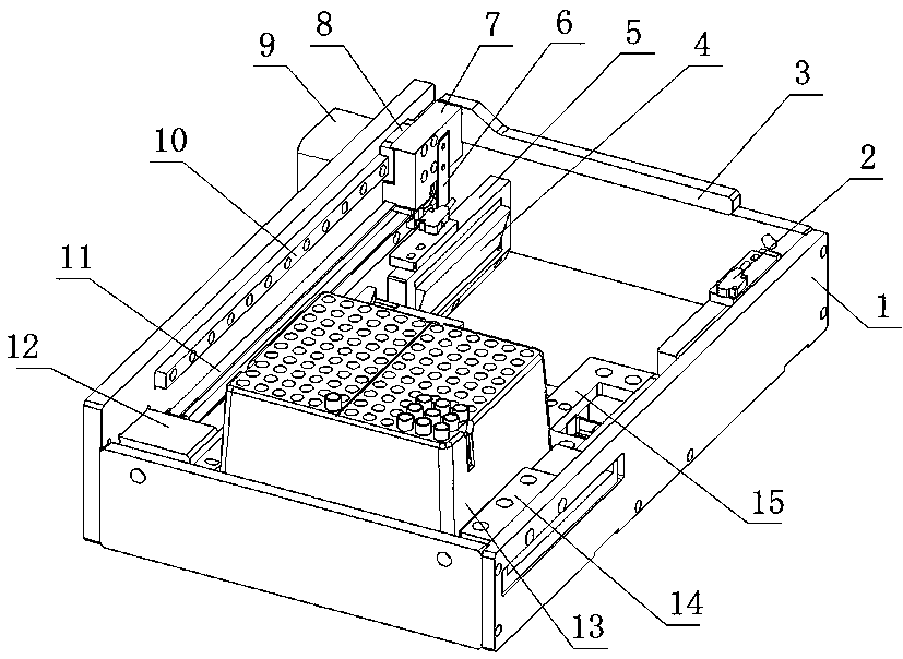
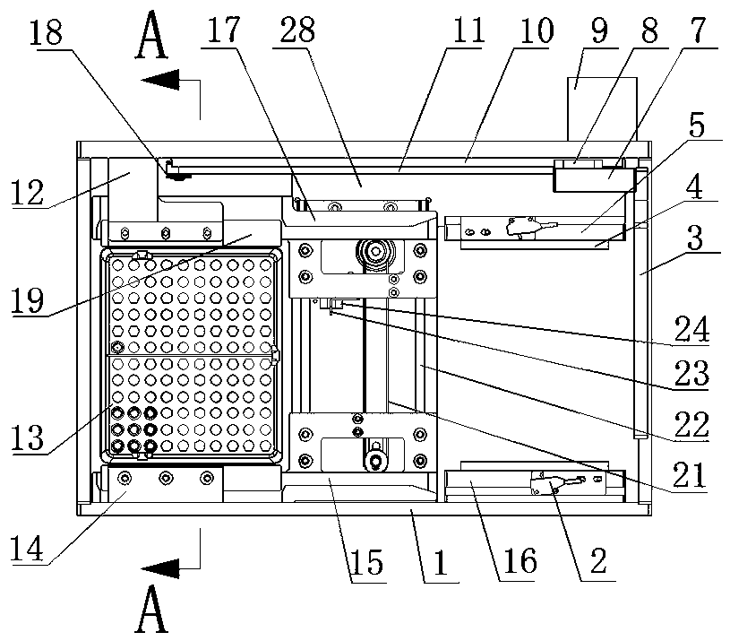
[0044] like Figure 1-3 As shown in the figure, an automatic loading device for a material box includes an enclosure 1 formed by four rectangular plates installed end to end. The inner area of ​​the enclosure 1 is sequentially divided into a feeding position, a guiding position and a positioning position from right to left. It also includes a bottom plate 28 installed at the bottom of the enclosure 1, a non-return mechanism used to support the material box 13, a push rod mechanism used to push the material box 13 from the feeding position to the positioning position, and the material box 13. 13. Guiding and positioning mechanism for guiding, positioning and discharging;

[0045] like Figure 9-13 As shown in the figure, the non-return...


PUM


Abstract

The invention relates to an automatic material box loading device and belongs to the technical field of material box transporting devices. The device comprises an enclosing plate formed by mounting four rectangular plates end to end. The internal area of the enclosing plate is partitioned into a feeding position, a guide position and a positioning position from right to left in sequence. The device further comprises a bottom plate mounted at the bottom of the enclosing plate, a check mechanism used for supporting a material box, a push rod mechanism used for pushing the material box from the feeding position to the positioning position, and a guide positioning mechanism used for guiding, positioning and discharging the material box. By arranging the push rod mechanism and the guide positioning mechanism, the material box is stably conveyed to the positioning position, meanwhile, the material box can be discharged after being positioned, the whole process of guiding, positioning and discharging can be completed through a power portion only, the requirement for the precision of the power portion is lower, the time for adjusting multiple power for mutual cooperation after mounting iscompleted is saved, power is simplified, and the equipment cost is lowered.

Description

technical field [0001] The invention relates to the technical field of material box transportation devices, and in particular to an automatic material box loading device. Background technique [0002] In automated medical inspection equipment, the degree of automation of material transportation and the length of the takt time for the equipment to complete transportation have become important indicators. For orderly transportation, the automatic transportation equipment of the material box needs to complete the single feeding, positioning and discharging actions of the material box. The material box transportation equipment in the prior art needs a supporting power mechanism to complete each action. The equipment cost is high, and at the same time, the stability of the material box must be ensured during the entire transportation process to avoid dumping of the materials in the material box. Therefore, the entire transportation process requires higher accuracy of the power me...

Claims


Application Information

Patent Timeline
Patent Type & Authority Applications(China)
IPC IPC(8): B65G47/82B65G25/08B65G47/24
CPCB65G25/08B65G47/24B65G47/82
Inventor 张立海孙启鹏王吉宁王峰苏桂香董飒英
Owner YANTAI ADEKANG BIOTECHNOLOGY CO LTD
Learn More