
Implant tooth structure based on SLM forming and forming method thereof

A molding method and dental implant technology, which is applied in the fields of dental implants, dentistry, and dental prostheses, can solve the problems of prolonging the treatment period of patients, achieve the effects of increasing the success rate of implantation, improving initial stability, and shortening the treatment period

Pending Publication Date: 2020-01-14
ZHEJIANG UNIV
View PDF1 Cites 0 Cited by
  • Summary
  • Abstract
  • Description
  • Claims
  • Application Information

AI Technical Summary

Problems solved by technology

Similarly, because the implant and the patient's alveolar socket cannot be completely matched, the implant cannot be implanted immediately after the patient's tooth root is pulled out, and the implant needs to go through the recovery process of the alveolar socket to make the shape of the alveolar socket relatively stable before implanting the implant. Greatly prolong the treatment cycle of patients

Method used


Image

  • Implant tooth structure based on SLM forming and forming method thereof
  • Implant tooth structure based on SLM forming and forming method thereof
  • Implant tooth structure based on SLM forming and forming method thereof

Examples


Embodiment 1

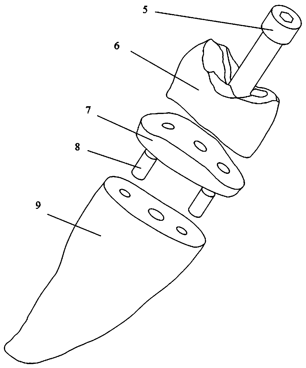
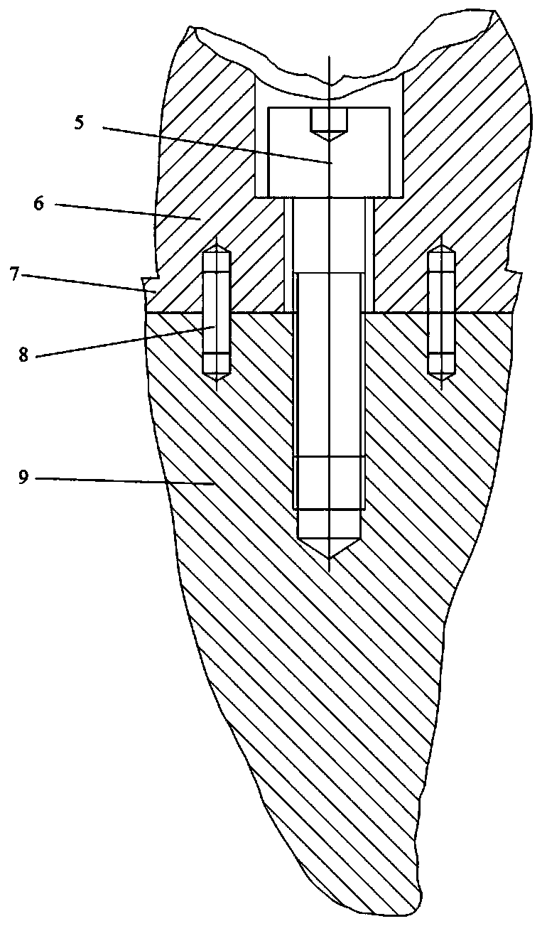
[0037] Such as figure 2 and image 3 As shown, this embodiment provides a dental implant structure based on SLM molding, including a tooth root 9 for implanting the implant in the alveolar socket in the later stage, and a neck 7 for sealing with the gum after the implantation of the abutment in the later stage and the three parts of the crown 6 meshing with the normal teeth; the crown and the neck together constitute the abutment structure of the clinical implant; the abutment structure is provided with a counterbore and at least two first positioning pin holes, so A threaded hole and a second positioning pin hole corresponding to the first positioning pin hole are processed on the root of the tooth; the screw 5 is screwed into the threaded hole after passing through the countersunk hole, and the first positioning pin hole and the second positioning pin hole are installed. Locating pin 8.

Embodiment 2

[0039] This embodiment provides the molding method of the dental implant structure of Embodiment 1, which method is based on SLM molding, and the specific method includes the following steps:

[0040] S1. Firstly, it is necessary to establish a personalized implant model according to the patient's teeth.

[0041] First, a CT scan of the patient's teeth is required. After the CT scan, the CT file is layered, and the tooth part and the soft tissue part are divided according to the gray value that cannot be tolerated. After processing the CT image, a model of the entire tooth can be obtained.

[0042]S2. After obtaining the tooth model, the tooth model needs to be divided into three parts according to the actual situation of the patient, namely: root 9 , neck 7 and crown 6 . The root of the tooth is used for implants to be placed in the alveolar socket in the later stage to cooperate with the alveolar socket. At the same time, the osseointegration in the later stage is also co...


PUM


Abstract

The invention discloses an implant tooth structure based on SLM forming and a forming method thereof. The implant tooth structure comprises a tooth root used for implanting an implant into an alveolarsocket in a later period, a neck part used for making contact with gingiva to play a sealing role after an abutment is implanted in the later period, and a dental crown meshed with normal teeth. Thedental crown and the neck part jointly form an abutment structure of the clinical implant; wherein a counterbore and at least two first positioning pin holes are formed in the abutment structure, anda threaded hole and second positioning pin holes corresponding to the first positioning pin holes are machined in the tooth root; a screw penetrates through the counterbore and then is screwed into the threaded hole, and a positioning pin is installed between the first positioning pin hole and the second positioning pin hole. The invention further provides the forming method of the structure, thestructure obtained through forming greatly improves the initial stability of the implant and shortens the treatment period of a patient, meanwhile, the success rate of implantation is increased, and the pain of the patient is relieved.

Description

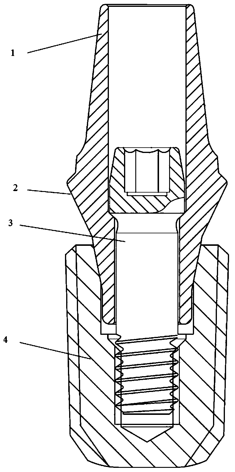
technical field [0001] The invention belongs to the technical field of oral medical devices, in particular to a dental implant structure based on SLM molding and a molding method thereof. Background technique [0002] With the development of science and technology and the improvement of human living standards, people gradually pay more attention to oral health. Tooth loss is one of the most serious oral problems and the most common one that often occurs in people. The most effective and ideal way to solve tooth loss is dental implants, and titanium, as a metal with better biocompatibility, has naturally become the first choice for implant materials. [0003] Existing commercial implants such as figure 1 As shown (patent CN 108852539 A), it mainly consists of abutment, fixing screw 3 and threaded implant 4. Wherein, the abutment mainly includes two parts, the small crown 1 and the neck 2 . The role of the small crown is mainly for the fixation of the crown. After the abut...

Claims


Application Information

Patent Timeline
Patent Type & Authority Applications(China)
IPC IPC(8): A61C8/00A61C13/00
CPCA61C8/0037A61C13/0004A61C13/0018
Inventor 祝毅李健王慧明余梦飞余晓雯
Owner ZHEJIANG UNIV
Learn More