
Plasma jet device

A plasma and jet device technology, applied in the field of plasma generation, can solve the problems of automatic adjustment of jet size, jet instability, unfavorable effective application of plasma, etc., and achieve reliable adjustment effect

Pending Publication Date: 2020-01-10
SHANGHAI UNIV OF ENG SCI
View PDF0 Cites 2 Cited by
  • Summary
  • Abstract
  • Description
  • Claims
  • Application Information

AI Technical Summary

Problems solved by technology

[0003] Most of the current plasma jet devices use artificial methods to adjust the size of the jet, which cannot automatically adjust the size of the jet according to the needs, resulting in unstable output of the jet, which is not conducive to the effective application of plasma

Method used


Image

  • Plasma jet device
  • Plasma jet device
  • Plasma jet device

Examples


Embodiment Construction

[0023] The present invention will be described in detail below in conjunction with the accompanying drawings and specific embodiments.

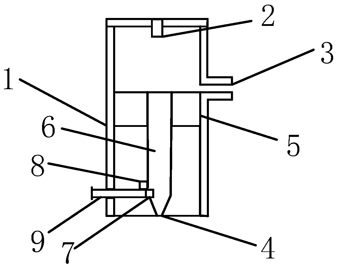
[0024] Such as figure 1 As shown, a plasma jet device includes a housing 1, a waveguide 2 and an inner guide 6 are installed in the housing 1, and a spout 4 communicating with the inner guide 6 is provided on the outer housing 1, and the inner guide 6 is located at the end of the waveguide 2. Below, there is a cavity between the inner conduit 6 and the waveguide 2, the cavity is provided with an air inlet 3 that can be closed and opened, and sealing blocks 5 are installed on both sides of the bottom of the cavity, and the inner conduit 6 is installed on two Between the sealing blocks 5;

[0025] One end of the waveguide 2 is connected to the microwave power supply 12, and the spout 4 is provided with a telescopic movable metal sheet 7. When the metal sheet 7 is in the initial position, the inner guide 6 is fully coupled with the metal sheet ...


PUM


Abstract

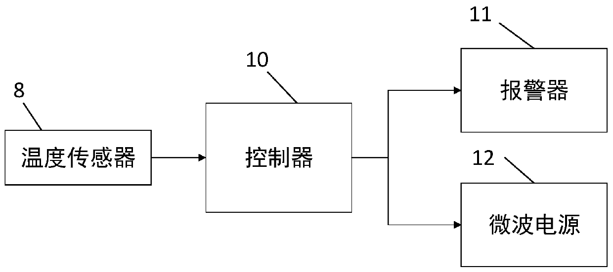
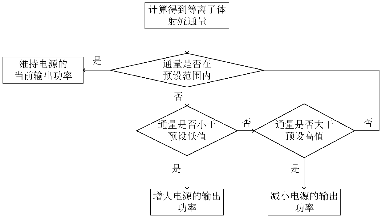
The invention relates to a plasma jet device comprising a shell. A waveguide and an inner conduit are installed in the shell. One end of the waveguide is connected with a microwave power supply. A cavity is arranged between the inner conduit and the waveguide. The cavity is provided with an air inlet which can be closed and opened. The shell is provided with a nozzle which is conducted with the inner conduit. A telescopic metal sheet is arranged at the nozzle. The metal sheet is in contact with a temperature sensor. The temperature sensor is connected with a controller. The controller is alsoconnected with the power supply and an alarm respectively. Compared with the devices in the prior art, the size of the plasma jet is positively relate to the output power of the power supply, the telescopic metal sheet, the temperature sensor and the controller are arranged and the plasma jet flux can be calculated and the output power of the power supply can be automatically adjusted so that thepurpose of autonomously adjusting the plasma jet size can be realized and the stability of the output plasma jet can be guaranteed.

Description

technical field [0001] The invention relates to the field of plasma generation, in particular to a plasma jet device. Background technique [0002] Plasma is the partial or complete ionization of gas molecules after gaining energy, and finally reaches the plasma state. The gas in the plasma state is quasi-electrically neutral, that is, it has equal and opposite charges under the condition of macroscopic space-time scale. The plasma temperature generated by atmospheric pressure plasma jet technology is low and the concentration of active substances is high, so it is widely used in material modification, sterilization, environmental protection and other aspects. [0003] Most of the current plasma jet devices use artificial methods to adjust the size of the jet, which cannot automatically adjust the size of the jet according to the needs, resulting in unstable output of the jet, which is not conducive to the effective application of plasma. Contents of the invention [000...

Claims


Application Information

Patent Timeline
Patent Type & Authority Applications(China)
IPC IPC(8): H05H1/00H05H1/24G01F1/68G01K7/00
CPCH05H1/0068H05H1/24G01F1/68G01K7/00
Inventor 邵飞帆段倩倩
Owner SHANGHAI UNIV OF ENG SCI
Learn More