An emergency power-off device for electrical automation equipment failure

A technology for electrical automation and equipment failure, which is applied to the power device, electrical components, circuits, etc. inside the switch, and can solve the problems of easy aging of parts, danger, and failure of limit devices, so as to improve safety performance and avoid aging rebound , design reasonable effect

Active Publication Date: 2021-06-25
GUANGDONG OCEAN UNIVERSITY
View PDF14 Cites 1 Cited by
  • Summary
  • Abstract
  • Description
  • Claims
  • Application Information

AI Technical Summary

Problems solved by technology

[0005] The object of the present invention is to provide a kind of emergency power-off device for electrical automation equipment failure, to solve the existing power-off switch proposed in the above-mentioned background technology, the operation method is to press the button down, so that the two groups of contact pieces that are powered are disconnected, thereby To achieve the purpose of power-off, after pressing down, a corresponding limit device is generally set to prevent the shrapnel from rebounding automatically. Because the internal parts of the device are easy to age, it is easy to cause the limit device to fail after long-term use, which is easy to cause certain damage. Dangerous; because the device shell structure of the device cannot be completely sealed, and the contact piece is used for a long time, it is easy to oxidize after contact with air, and the surface rust and breakage will affect the conductivity of the contact piece, which is likely to cause abnormal open circuit phenomenon the occurrence of problems

Method used


Image

  • An emergency power-off device for electrical automation equipment failure
  • An emergency power-off device for electrical automation equipment failure
  • An emergency power-off device for electrical automation equipment failure

Examples


Embodiment Construction

[0027] The following will clearly and completely describe the technical solutions in the embodiments of the present invention with reference to the accompanying drawings in the embodiments of the present invention. Obviously, the described embodiments are only some, not all, embodiments of the present invention. Based on the embodiments of the present invention, all other embodiments obtained by persons of ordinary skill in the art without making creative efforts belong to the protection scope of the present invention.

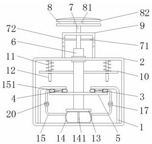
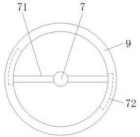
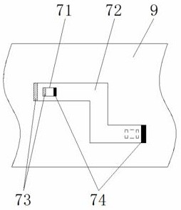
[0028] see Figure 1-7 , the present invention provides a technical solution: an emergency power-off device for electrical automation equipment failure, including a metal sheet 1, a device casing 2, a first contact sheet 3, a second contact sheet 4, a metal plate 5, a displacement rod 6, a control Rod 7, clamping rod 71, rod groove 72, first magnetic sheet 73, second magnetic sheet 74, top plate 8, vertical shaft 81, pressing plate 82, protective shell 9, rese...


PUM


Abstract

The invention discloses an emergency power-off device for failure of electrical automation equipment, which comprises a metal sheet, a first contact sheet, a second contact sheet and a metal sheet, the metal sheet is fixed inside the device casing, the first connecting air pipe and The second connecting air pipes are distributed in an "L" shape structure, and a snap ring is arranged outside the middle vertical part of the two. The snap ring is located inside the device shell, and the snap ring is connected to one end of the fixing rod. The snap ring A clamping plate is arranged on the opposite surface of the ring, a sleeve is rotatably connected to the center of the horizontal plate, and the surface of the sleeve is hinged to the driving rod, and the sleeve is connected to the knob through the rotating rod. The emergency power-off device for failure of electrical automation equipment can stably limit and fix the up and down movement of the metal plate, and is very convenient to operate. At the same time, it can close the gas passage by locking the connecting trachea while using the air bag for sealing protection of the contact piece. way to improve the safety performance of device operation.

Description

technical field [0001] The invention relates to the technical field related to electrical equipment, in particular to an emergency power-off device for failure of electrical automation equipment. Background technique [0002] The emergency power-off device refers to the equipment that uses electric or manual methods to cut off the power of the energized line. When the electrical equipment is in operation, the emergency power-off device is an essential device. When the equipment fails, in order to ensure the power-off To ensure the reliability of power operation, people generally use manually operated power-off devices for power-off operations, but the existing power-off devices have the following disadvantages in actual use: [0003] 1. The operation method of the existing power-off switch is to press the button down to disconnect the two sets of contacts that are powered on, so as to achieve the purpose of power-off. After pressing down, a corresponding limit device is gene...

Claims


Application Information

Patent Timeline
Patent Type & Authority Patents(China)
IPC IPC(8): H01H3/02H01H3/24
CPCH01H3/022H01H3/24
Inventor 李一峰林景东张瑛
Owner GUANGDONG OCEAN UNIVERSITY
Why Eureka
Try Eureka