
Display panel driving method, display driving device and electronic equipment

A technology of a display panel and a driving method, which is applied in the fields of display panel driving, electronic equipment, and display driving devices, and can solve problems affecting the display quality of a display screen, etc.

Active Publication Date: 2020-01-10
WUHAN TIANMA MICRO ELECTRONICS CO LTD
View PDF18 Cites 6 Cited by
  • Summary
  • Abstract
  • Description
  • Claims
  • Application Information

AI Technical Summary

Problems solved by technology

As a result, the display effect of the area where the sensor module is placed is inconsistent with the display effect of the normal display area. The boundary between the two is obvious, which affects the overall display quality of the display screen.

Method used


Image

  • Display panel driving method, display driving device and electronic equipment
  • Display panel driving method, display driving device and electronic equipment
  • Display panel driving method, display driving device and electronic equipment

Examples


Embodiment Construction

[0042] The present invention will be further described in detail below in conjunction with the accompanying drawings and embodiments. It should be understood that the specific embodiments described here are only used to explain the present invention, but not to limit the present invention. In addition, it should be noted that, for the convenience of description, only some structures related to the present invention are shown in the drawings but not all structures.

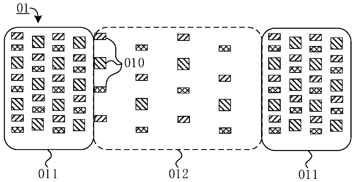
[0043] In the prior art, in order to achieve the purpose of integrating the display panel with other sensor modules while achieving a high screen-to-body ratio, the display panel 01 is usually set to include a normal display area 011 and a sensor setting area 012. The sensor setting area 012 can also be called It is the semi-permeable area 012. Since the light-emitting elements 010 have a shielding effect on light, considering that the structures of the light-emitting elements 010 are all the same, the more the li...


PUM


Abstract

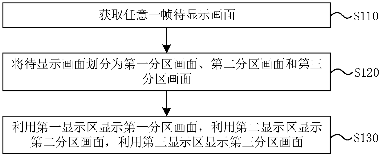
The embodiment of the invention discloses a display panel driving method, a display driving device and electronic equipment. The driving method comprises the following steps: acquiring any frame of to-be-displayed picture; dividing the picture to be displayed into a first partition picture, a second partition picture and a third partition picture; displaying the first partition picture by using the first display area, displaying the second partition picture by using the second display area, and displaying the third partition picture by using the third display area, wherein in the same frame ofpicture to be displayed, the sub-pixel density A1 for displaying the first partition picture, the sub-pixel density A2 for displaying the second partition picture and the sub-pixel density A3 for displaying the third partition picture meet the condition that A2 is larger than A1 and smaller than or equal to A3; the sub-pixels of the second display area comprise the first sub-pixels and the secondsub-pixels, and the display brightness L21 of the first sub-pixels and the display brightness L22 of the second sub-pixels meet the condition that L21 is larger than L22. According to the technical scheme, transition of the image quality and the brightness in the to-be-displayed image can be achieved through the second display area, and therefore the overall display quality can be improved.

Description

technical field [0001] The present invention relates to the field of display technology, in particular to a driving method of a display panel, a display driving device and electronic equipment. Background technique [0002] With the development of display technology, more and more display panels and display devices are applied in people's daily life and work. In order to improve user experience, the display panel structure can also be integrated with sensor modules, such as cameras, infrared sensors, etc., to integrate functions such as taking pictures and infrared detection. [0003] On this basis, in order to meet a higher screen-to-body ratio, light-emitting elements can also be placed in the area of ​​the display panel where the sensor module is correspondingly arranged. In order to ensure that the sensor module can work normally, the density of the light emitting elements in the area where the sensor module is placed is generally smaller than the density of the light e...

Claims


Application Information

Patent Timeline
IPC IPC(8): G09G3/36G09G3/3208
CPCG09G3/3607G09G3/3208G09G3/36G09G2354/00G09G2340/0407G09G2320/0686H10K59/353G06T7/143
Inventor 黑亚君周井雄周瑞渊
Owner WUHAN TIANMA MICRO ELECTRONICS CO LTD
Learn More