
Strength detection device for glass processing

A technology for strength detection and glass, which is applied in the direction of measuring devices, strength characteristics, and the use of stable tension/pressure to test the strength of materials, etc. It can solve the problems of inconvenient glass slag cleaning and inconvenient glass placement, so as to improve convenience and improve Sufficiency, safety-enhancing effect

Inactive Publication Date: 2020-01-10
徐州市威固特种玻璃有限公司
View PDF0 Cites 5 Cited by
  • Summary
  • Abstract
  • Description
  • Claims
  • Application Information

AI Technical Summary

Problems solved by technology

[0003] In the process of glass processing, in order to ensure the quality of the glass, it is necessary to perform strength testing on it, and a strength testing device will be used. However, the existing glass strength testing device is not convenient for placing the glass during use. At the same time, it is not convenient to clean up the glass slag after detection, so it is necessary to design a strength detection device for glass processing to solve the above problems

Method used


Image

  • Strength detection device for glass processing
  • Strength detection device for glass processing
  • Strength detection device for glass processing

Examples


Embodiment 1

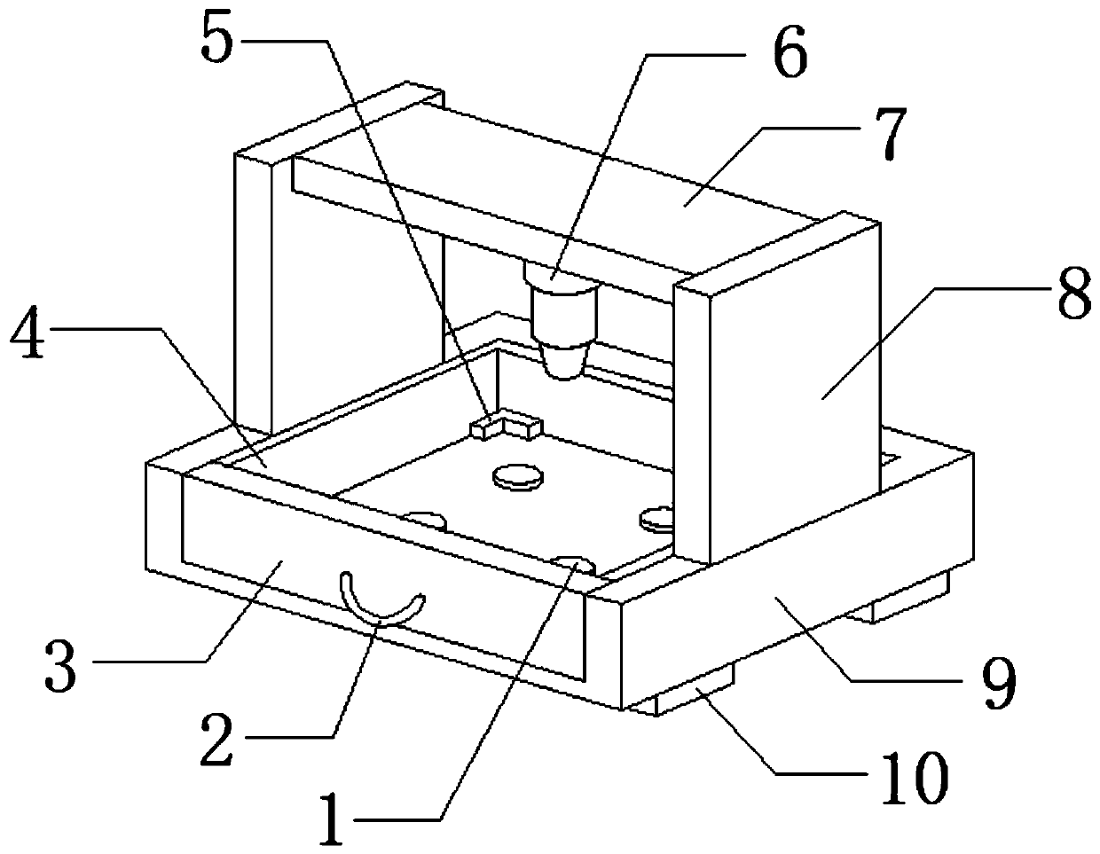
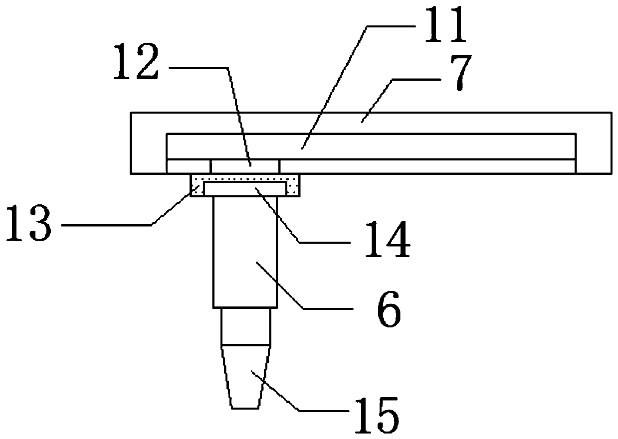
[0024] refer to Figure 1-2 , a strength detection device for glass processing, comprising a support base 9 and four support pads 10, the four support pads 10 are respectively installed on the bottom four-corner outer walls of the support base 9 by bolts, and the outer wall at one end of the top of the support base 9 is provided with a first Groove, and the inner wall of the first groove is plugged with a slot plate 4, the outer wall at one end of the slot plate 4 is connected with the first support plate 3 by bolts, the bottom four corners inner walls of the slot plate 4 are all connected with limited blocks by bolts, the slot plate The bottom inner wall of 4 is connected with four rubber pads 1 distributed in a rectangular array through bolts, and the middle outer wall at one end of the first support plate 3 is connected with a pull handle 2 through a hinge.

[0025] In the present invention, the outer walls on both sides of the top of the support base 9 are connected with v...

Embodiment 2

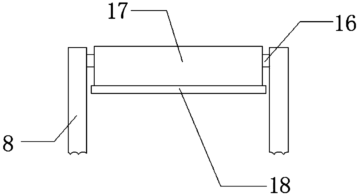
[0027] refer to Figure 1-3 , a strength detection device for glass processing, which also includes the same rotating rod 16 installed on the outer wall of the top and end of the adjacent side of the two splints 8 through bearings, and the peripheral outer wall of the rotating rod 16 is wound with a rolling cloth 17 through a spring , the outer wall of the bottom of the roll cloth 17 is connected with a support rod 18 by bolts. During the process of testing the glass, the roll cloth 17 can be pulled down by the support rod 18, so as to avoid the splash of crushed glass fragments and cause harm to the user. Injury, improve the safety of device use.


PUM


Abstract

The invention discloses a strength detection device for glass processing. The device comprises a supporting base and four supporting pads; the four supporting pads are installed on the outer walls ofthe four corners of the bottom of the supporting base through bolts respectively; a first groove is formed in the outer wall of one end of the top of the supporting base; a groove plate is inserted into the inner wall of the first groove; a first supporting plate is fixedly installed on the outer wall of one end of the groove plate; and limiting blocks are fixedly installed on the inner walls of the four corners of the bottom of the groove plate respectively. According to the strength detection device for glass processing provided by the invention, the first groove is formed in the supportingbase; the groove plate is inserted into the first groove; the limiting blocks and rubber pads are arranged in the groove plate; glass can be effectively limited and fixed through the limiting blocks,so that the slide deviation of the glass in the detection process is avoided, and therefore, detection stability is improved; and, the groove plate can be pulled out through a pulling handle, so thatthe glass is disassembled and assembled, and therefore, the convenience of glass detection and replacement is improved.

Description

technical field [0001] The invention relates to the technical field of glass processing, in particular to a strength detection device for glass processing. Background technique [0002] Glass is an amorphous solid that can maintain a certain shape. It is a substance obtained by gradually cooling the glass paste melt and increasing its temperature. In today's society, glass has become popular in people's lives, and glass products can be seen everywhere, such as drinking glasses, glass windows, glass doors, screen protection glass on computer monitors, and glass buildings. Talk about how the glass for electronics and displays is processed by glass processing factories. [0003] In the process of glass processing, in order to ensure the quality of the glass, it is necessary to perform strength testing on it, and a strength testing device will be used. However, the existing glass strength testing device is not convenient for placing the glass during use. At the same time, it i...

Claims


Application Information

Patent Timeline
IPC IPC(8): G01N3/08G01N3/02
CPCG01N3/02G01N3/08G01N2203/0003G01N2203/0019G01N2203/0087G01N2203/0252G01N2203/0282G01N2203/0676
Inventor 宋庆
Owner 徐州市威固特种玻璃有限公司
Learn More