
A Method for Acquiring Temperature Drift Compensation Parameters of Uncooled Infrared Thermal Imaging

An uncooled infrared and temperature drift compensation technology, applied in the field of infrared thermal imaging, to achieve low environmental and self requirements, good compensation effect, and good effect

Active Publication Date: 2020-08-25
HARGLO APPLIED LASER TECH INST CO LTD
View PDF8 Cites 0 Cited by
  • Summary
  • Abstract
  • Description
  • Claims
  • Application Information

AI Technical Summary

Problems solved by technology

[0005] The problem to be solved by the present invention is to provide a method for acquiring temperature drift compensation parameters of uncooled infrared thermal imaging, which solves the accidental problem of vertical stripes appearing in the imaging screen and general parameter acquisition methods due to the change of FPA itself with time

Method used


Image

  • A Method for Acquiring Temperature Drift Compensation Parameters of Uncooled Infrared Thermal Imaging
  • A Method for Acquiring Temperature Drift Compensation Parameters of Uncooled Infrared Thermal Imaging
  • A Method for Acquiring Temperature Drift Compensation Parameters of Uncooled Infrared Thermal Imaging

Examples


Embodiment Construction

[0041] It should be noted that, in the case of no conflict, the embodiments of the present invention and the features in the embodiments can be combined with each other.

[0042] In describing the present invention, it should be understood that the terms "center", "longitudinal", "transverse", "upper", "lower", "front", "rear", "left", "right", " The orientations or positional relationships indicated by "vertical", "horizontal", "top", "bottom", "inner" and "outer" are based on the orientations or positional relationships shown in the drawings, and are only for the convenience of describing the present invention and Simplified descriptions, rather than indicating or implying that the device or element referred to must have a particular orientation, be constructed and operate in a particular orientation, and thus should not be construed as limiting the invention. In addition, the terms "first", "second", etc. are used for descriptive purposes only, and should not be understood ...


PUM


Abstract

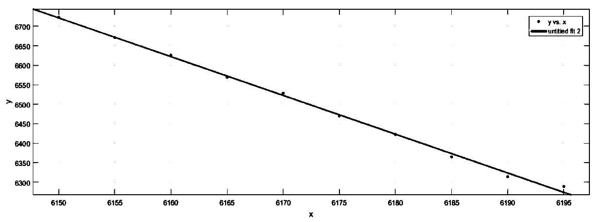
The invention provides a method for obtaining temperature drift compensation parameters of uncooled infrared thermal imaging, which belongs to the technical field of infrared thermal imaging, and includes the following steps: S1, collecting original image data of a movement under a stable radiation source every five FPAs, Record the current FPA value; S2. Preprocess the original pixel values ​​of the obtained multiple sets of images, eliminate the fixed blind pixels and flickering blind pixels in the pixels, and perform linear one-time fitting on each pixel data respectively, using the least squares method , output the best fitting parameter K of the movement temperature drift; S3, optimize the code, shorten the parameter calculation time; S4, calculate the maximum value of the image, and at the same time qualitatively calculate the non-uniformity of the image in real time, and verify the correctness of the parameters; S5, the parameters obtained by fitting Add it to the host computer to test the effect of parameter compensation. The invention solves the accidental problem of vertical stripes appearing in the imaging picture and general parameter acquisition method due to the change of FPA itself with time.

Description

technical field [0001] The invention belongs to the technical field of infrared thermal imaging, and relates to a method for acquiring temperature drift compensation parameters of uncooled infrared thermal imaging. Background technique [0002] Due to defects in manufacturing materials and processes, obstacles to signal charge transmission, etc., the infrared focal plane array device inevitably has non-uniformity. The principle of the focal plane detector is that an array of photosensitive elements is arranged on the focal plane. The emitted infrared rays are imaged on these photosensitive elements on the focal plane of the system through the optical system, and the detector converts the received optical signal into an electrical signal, performs integral amplification, sample and hold, and finally sends it to the monitoring system through the output buffer and multiplex transmission system To form an image, the use of infrared focal plane array (IRFPA) can simplify or cance...

Claims


Application Information

Patent Timeline
Patent Type & Authority Patents(China)
IPC IPC(8): G01J5/00
CPCG01J5/00G01J2005/0077G01J5/80
Inventor 李婷张志强于旭东张剑
Owner HARGLO APPLIED LASER TECH INST CO LTD
Learn More