Mechanical steel pipe belling machine

A flaring machine and mechanical technology, applied in the field of steel pipe flaring machines, can solve the problems of increasing the difficulty of flaring, easy sliding and translocation, poor safety, etc., and achieve the goal of improving the flaring efficiency, reducing labor intensity, and reasonable structural design Effect

Active Publication Date: 2021-05-04
安徽省荣源智能科技有限公司
View PDF9 Cites 0 Cited by
  • Summary
  • Abstract
  • Description
  • Claims
  • Application Information

AI Technical Summary

Problems solved by technology

In the actual steel pipe flaring process, the flaring machines currently on the market are all manual, with a low degree of automation, which greatly affects the flaring efficiency, increases the labor intensity of the operator, and has poor safety. Steel pipe processing It is easy to slide and translocate during the process, which increases the difficulty of flaring and needs further improvement

Method used


Image

  • Mechanical steel pipe belling machine
  • Mechanical steel pipe belling machine
  • Mechanical steel pipe belling machine

Examples


Embodiment Construction

[0019] The following will clearly and completely describe the technical solutions in the embodiments of the present invention with reference to the accompanying drawings in the embodiments of the present invention. Obviously, the described embodiments are only some, not all, embodiments of the present invention. Based on the embodiments of the present invention, all other embodiments obtained by persons of ordinary skill in the art without creative efforts fall within the protection scope of the present invention.

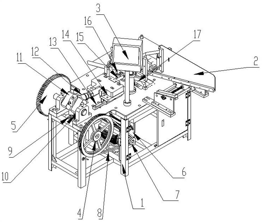
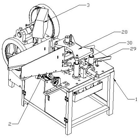
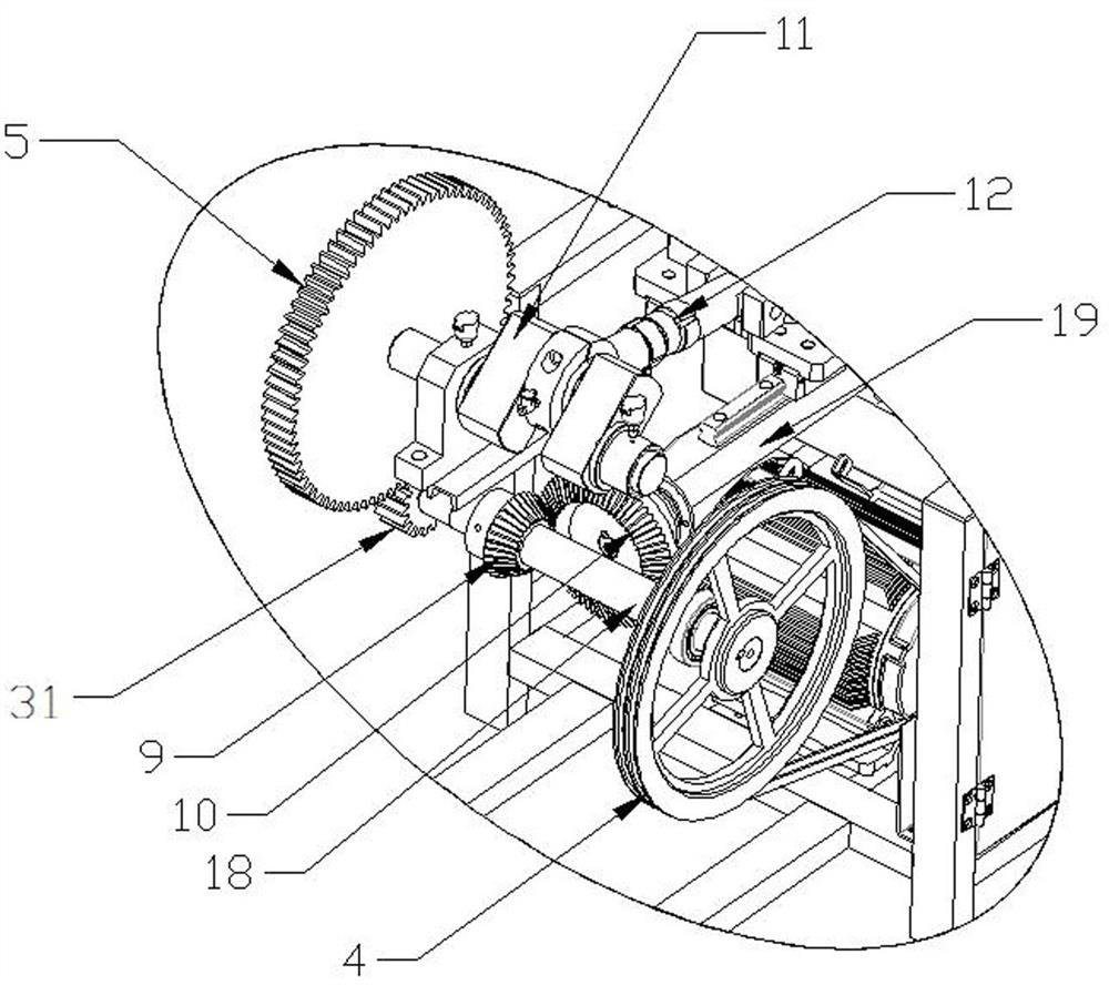
[0020] see Figure 1-5 As shown, the present embodiment is a mechanical steel pipe flaring machine, comprising a frame 1, the top right side of the frame 1 is connected with a material rack 2, the bottom of the material frame 2 is provided with a material delivery plate 17, and the top of the frame 1 is equipped with a The control box 3, the left side of the front face of the frame 1 is connected with a large pulley 4, the lower surface of the frame 1 is connected ...


PUM

PropertyMeasurementUnit
lengthaaaaaaaaaa

Abstract

The invention discloses a mechanical steel pipe flaring machine, which comprises a frame. The top right side of the frame is connected with a material rack, the bottom of the material frame is provided with a material delivery plate, the top of the frame is equipped with a control box, and the front end of the frame is left. The side rotation is connected with a large pulley, the lower surface of the frame is connected with a motor, the power output end of the motor is connected with a small pulley, a V-belt is set between the large pulley and the small pulley, and a gear is installed on the left side of the rear end of the frame. The center of the gear is connected to the crankshaft, and the middle part of the crankshaft is connected to the connecting rod. The other end of the connecting rod is hinged to the slider through the pin shaft. The bottom of the slider is provided with a matching linear guide rail. , the right side of the flare punch is provided with a flare die. The invention has reasonable structural design and convenient operation, realizes the automation of the pipe material processing procedure, greatly improves the flaring efficiency of the steel pipe, reduces the labor intensity of operators, is safe and reliable, and is suitable for popularization and use.

Description

technical field [0001] The invention relates to the technical field of steel pipe flaring machines, in particular to a mechanical steel pipe flaring machine. Background technique [0002] During the layout of the pipeline, if the pipeline is not long enough and needs to be butted, the usual method is to use a direct joint to connect two straight pipes to each other, and then weld them to death after the butt joint is completed, but the stress at the weld is relatively concentrated. Welds are prone to weld cracking, which causes leakage. Therefore, in order to reduce the number of welds, the existing method is to expand one of the pipes, insert the other pipe into the expanded pipe, and then Butt welding, compared with the traditional process, there is less direct joint, so there is one less weld, so it is safer, so the steel pipe flaring technology came into being. [0003] With the continuous development of the construction machinery industry, steel pipe flaring technology...

Claims


Application Information

Patent Timeline
Patent Type & Authority Patents(China)
IPC IPC(8): B21D39/08B21D43/02
CPCB21D39/08B21D43/006B21D43/02
Inventor 叶紫淳
Owner 安徽省荣源智能科技有限公司
Why Eureka
Try Eureka