Hydraulic guide pipe flaring machine

A flaring machine and conduit technology, which is applied to metal processing equipment, feeding devices, safety equipment, etc., can solve the problems of no positioning and clamping mechanism, fixture wear, and flaring accuracy decline, etc. The effect of flaring accuracy and improving work efficiency

Pending Publication Date: 2021-05-25
大连长丰实业总公司
View PDF0 Cites 0 Cited by
  • Summary
  • Abstract
  • Description
  • Claims
  • Application Information

AI Technical Summary

Problems solved by technology

[0002] Most of the existing hydraulic conduit flaring operations are manual clamping and clamping of the conduit, manual feeding, and a small part is hydraulic or electric semi-automatic clamping and clamping; at the same time, all related equipment is not equipped with positioning and clamping mechanisms, and the flaring The feed rate cannot be determined, and the feed rate can only be determined based on the experience of the operator. It cannot be guaranteed that the flared bell mouth of the hydraulic conduit meets the requirements of HB4-52-2002 (the aviation standard for hydraulic conduits), and the yield of hydraulic conduit flares is less than 50%, and with the increase of use time, the fixture wears out, resulting in a significant drop in flaring accuracy, and even the catheter cannot be clamped

Method used


Image

  • Hydraulic guide pipe flaring machine
  • Hydraulic guide pipe flaring machine
  • Hydraulic guide pipe flaring machine

Examples


Embodiment Construction

[0037] The present invention will be described in detail below with reference to the accompanying drawings and examples.

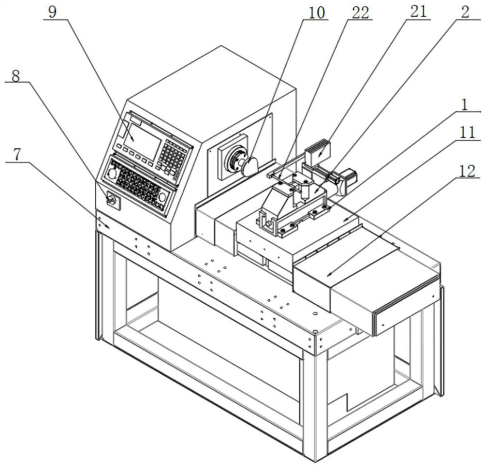
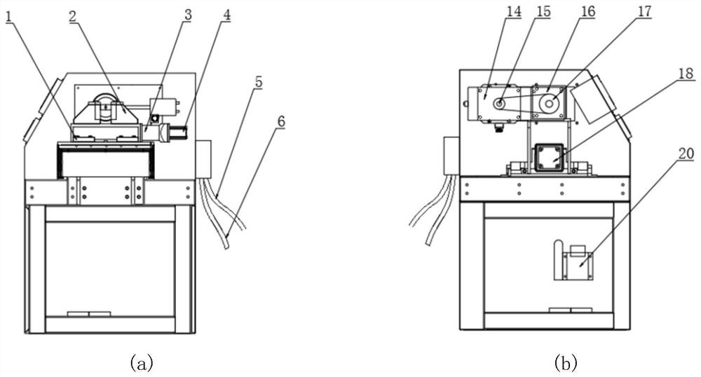
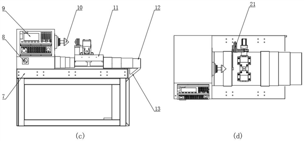
[0038] This embodiment provides a hydraulic conduit flaring machine, which can effectively determine the feed rate and ensure effective clamping of the hydraulic conduit. At the same time, the automatic flaring process can be realized by using the numerical control panel for numerical control.

[0039] The flaring machine includes: installation pressure plate 1, fixture 2, power cord 5, air source connection 6, base body 7, switch 8, numerical control panel 9, expansion cone 10, sliding plate A11, telescopic protective plate 12, protective plate mounting frame 13. Main shaft servo system, oil tank 20, hydraulic conduit positioning mechanism 21, ball screw A24, ball screw bearing support 25, linear guide 26, guide rail slider 27 and nut A28; fixture 2 includes: planetary reducer A3, Servo motor A4, pressing plate 202, clamping block 203, double-lock centeri...


PUM


Abstract

The invention discloses a hydraulic guide pipe flaring machine which comprises a clamp, a power line, a base body, a switch, a numerical control panel, a flaring cone, a slide carriage A, a main shaft servo system, an oil tank, a hydraulic guide pipe positioning mechanism, a ball screw A, a ball screw bearing support and a nut A, According to the flaring machine, a numerical control panel is adopted for controlling the flaring machine, it can be guaranteed that the flaring machining process is automatic in the whole process through the numerical control panel, the accurate machining feeding amount can be determined through cooperation of the hydraulic guide pipe positioning mechanism and the slide carriage A, and meanwhile, a clamp can effectively clamp a hydraulic guide pipe; and the size of a machined hydraulic guide pipe horn mouth is accurate, use is convenient and fast, the flaring efficiency is high, the yield is 90% or above, and the working efficiency is greatly improved.

Description

technical field [0001] The invention relates to the technical field of aviation mechanical equipment processing, in particular to a hydraulic conduit flaring machine. Background technique [0002] Most of the existing hydraulic conduit flaring operations are manual clamping and clamping of the conduit, manual feeding, and a small part is hydraulic or electric semi-automatic clamping and clamping; at the same time, all related equipment is not equipped with positioning and clamping mechanisms, and the flaring The feed rate cannot be determined, and the feed rate can only be determined based on the experience of the operator. It cannot be guaranteed that the flared bell mouth of the hydraulic conduit meets the requirements of HB4-52-2002 (the aviation standard for hydraulic conduits), and the yield of hydraulic conduit flares is less than 50%, and with the increase of the use time, the fixture wears out, which leads to a significant decrease in the flaring accuracy, and even t...

Claims


Application Information

Patent Timeline
Patent Type & Authority Applications(China)
IPC IPC(8): B21D41/02B21D43/00B21D55/00
CPCB21D41/02B21D43/003B21D55/00
Inventor 王民强李青张书绪田兵
Owner 大连长丰实业总公司
Why Eureka
Try Eureka