Die for flaring pipe fitting and manufacturing method thereof

A manufacturing method and mold technology, which is applied to the mold for pipe fitting expansion and its manufacturing field, can solve the problems of single expansion mold method, low precision of expansion mold, and irregular shape, so as to improve sizing accuracy and improve efficiency , The effect of good roundness of pipe fittings

Inactive Publication Date: 2022-07-08
温州正鑫管业有限公司
View PDF0 Cites 0 Cited by
  • Summary
  • Abstract
  • Description
  • Claims
  • Application Information

AI Technical Summary

Problems solved by technology

[0004] The present invention determines the diameter and the number of through holes on the positioning block according to the length of the positioning block, and corrects the diameter according to the outer diameter of the limit rod; determines the length of the connecting sleeve according to the length of the pipe joint, and then according to the connection The length of the sleeve determines the length of the flaring pipe body; the thickness of the positioning block is determined according to the hardness level of the positioning block to solve the single method of manufacturing the flaring mold in the prior art, and the processed flaring mold has low precision and irregular shape The problem

Method used


Image

  • Die for flaring pipe fitting and manufacturing method thereof

Examples


Embodiment Construction

[0073] The specific embodiments of the present invention will be described in further detail below with reference to the accompanying drawings and embodiments. The following examples are intended to illustrate the present invention, but not to limit the scope of the present invention.

[0074] In the description of this application, it should be understood that the terms "center", "upper", "lower", "front", "rear", "left", "right", "vertical", "horizontal", The orientation or positional relationship indicated by "top", "bottom", "inner", "outer", etc. is based on the orientation or positional relationship shown in the drawings, and is only for the convenience of describing the present application and simplifying the description, rather than indicating or implying The device or element referred to must have a particular orientation, be constructed and operate in a particular orientation, and therefore should not be construed as a limitation of the present application.

[0075]...


PUM


Abstract

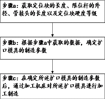
The invention relates to the technical field of dies, and discloses a die for pipe flaring and a manufacturing method thereof.The manufacturing method comprises the steps that a, the length of a positioning block, the outer diameter of a limiting rod, the length of a pipe joint and the hardness grade of the positioning block are obtained; b, according to the data obtained in the step a, manufacturing parameters of the flaring die are determined; c, after the manufacturing parameters of the flaring die are determined, the flaring die is machined and manufactured through a machining machine tool, the length of the connecting sleeve is determined according to the length of the pipe joint, and then the length of the flaring pipe body is determined according to the length of the connecting sleeve; the drift diameter and the number of the through holes in the positioning block are determined according to the length of the positioning block, and the drift diameter is corrected according to the outer diameter of the limiting rod; the thickness of the positioning block is determined according to the hardness grade of the positioning block, the pipe fitting flaring die machined through the manufacturing method can improve the sizing precision, the roundness of a flaring pipe fitting is good, and the pipe fitting flaring efficiency can be greatly improved.

Description

technical field [0001] The present invention relates to the technical field of molds, in particular to a mold for flaring a pipe fitting and a manufacturing method thereof. Background technique [0002] At present, pipelines are widely used in daily life as a transmission medium. Pipes have an irreplaceable role in the field of home appliances, automobiles, machine tools and other fields. However, when the open end of the pipeline needs to be fixedly connected, it is Pipes need to be connected by means of joints, and the mold that needs to be flared at this time will flare the pipes. [0003] In the prior art, the method of manufacturing the flaring mold generally adopts the method of directly placing the flaring mold on the processing machine tool, which cannot be adjusted according to the actual situation. Therefore, the prepared flaring mold is relatively simple, and the molding effect is not good. The precision of the processed flaring mold is also not accurate enough. ...

Claims


Application Information

Patent Timeline
Patent Type & Authority Applications(China)
IPC IPC(8): B21D37/20B21D41/02B21D37/10
CPCB21D37/20B21D41/02B21D37/10
Inventor 张周慧张武昌张弓长
Owner 温州正鑫管业有限公司
Why Eureka
Try Eureka