Online soot blowing device for waste heat boiler for sintering vertical cold furnace

A technology of waste heat boiler and soot blowing device, which is applied in the direction of combustion method, removal of solid residue, treatment of combustion products, etc. It can solve the problems of affecting boiler evaporation heat transfer efficiency, unknown blowing effect, insufficient pressure, etc., and achieves accurate Purging technology and implementation status monitoring, eliminating the possibility of water, increasing the effect of purging area

Active Publication Date: 2020-01-07
SHANGHAI MEISHAN IRON & STEEL CO LTD
View PDF6 Cites 1 Cited by
  • Summary
  • Abstract
  • Description
  • Claims
  • Application Information

AI Technical Summary

Problems solved by technology

[0004] The disadvantages of using industrial compressed air for purging are: because the temperature of the compressed air before entering the waste heat boiler is normal temperature, the temperature of the boiler’s high-pressure and low-pressure heating surfaces exceeds 100°C, and the temperature of the high-temperature evaporator is higher at about 400°C. Compressed air at normal temperature, Or compressed air with water directly enters the high-temperature heating surface for purging, (relative heat and cold exchange) will cause great equipment damage to the heating surface of the evaporator, seriously affect the service life of the waste heat boiler, affect the evaporation heat transfer efficiency of the boiler, and affect the steam quality
Conventional locking sound wave rapping and compressed air blowing have poor blowing effect on the evaporation heating surface of the waste heat boiler, the pressure is not enough, the blowing effect is not known, and the blowing situation cannot be seen intuitively; therefore, a new one is urgently needed Solution to the technical problem

Method used


Image

  • Online soot blowing device for waste heat boiler for sintering vertical cold furnace
  • Online soot blowing device for waste heat boiler for sintering vertical cold furnace
  • Online soot blowing device for waste heat boiler for sintering vertical cold furnace

Examples


Embodiment 1

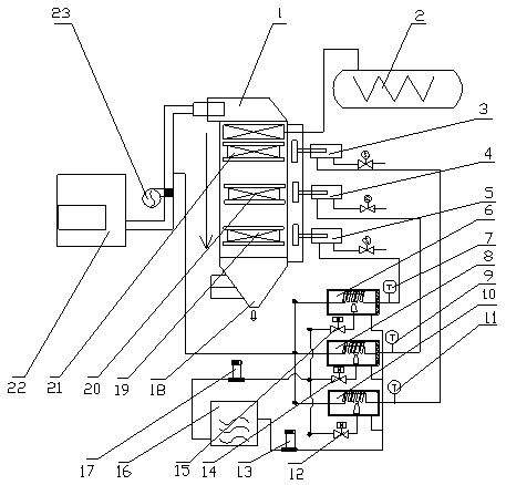
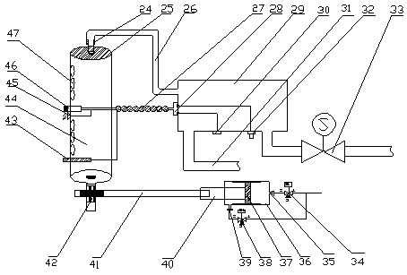
[0018] Example 1: see figure 1 , figure 2 , An online soot blowing device for a sintered vertical cooling waste heat boiler, the soot blowing device includes a waste heat boiler 1, a steam drum 2, a vertical cooling furnace 22, an induced draft fan 23, and a purge assembly. The waste heat boiler 1 adopts a vertical arrangement, and the steam The package 2 is installed on the top of the waste heat boiler 1 and arranged on the boiler support near the vertical cooling furnace 22. The purge assembly includes three purge devices, namely the high temperature purge device 3, the low temperature purge device 4 and the economizer purge device. Sweeping device 5, the waste heat boiler 1 is provided with a high temperature evaporator, a low temperature evaporator and an economizer evaporator, the high temperature evaporator is connected with a high temperature purge device, and the low temperature evaporator is connected with a low temperature purge device 4. The coaler 19 is connected to...


PUM


Abstract

The invention relates to an online soot blowing device for a waste heat boiler for a sintering vertical cold furnace. The soot blowing device comprises the waste heat boiler, a steam drum, the vertical cold furnace, a draft fan and a blowing assembly; the waste heat boiler is vertically arranged; the steam drum is arranged at the top part of the waste heat boiler; the waste heat boiler is arrangedon a boiler support adjacent to the vertical cold furnace; the blowing assembly includes three blowing devices, i.e., a high-temperature blowing device, a low-temperature blowing device and an economizer blowing device; a high-temperature evaporator, a low-temperature evaporator and an economizer evaporator are arranged in the waste heat boiler; one side of the bottom part of the waste heat boiler is provided with a cooling water tank; an outlet of the cooling water tank is additionally provided with a water pump; and an outlet of the water pump is still additionally provided with three groups of corresponding temperature adjustment assemblies. According to the scheme, the soot blowing device can automatically adjust in blowing direction, and is provided with temperature measuring equipment; and by additionally installing an endoscope, functions of monitoring the soot deposition condition and blowing soot online, and the like, can be realized.

Description

Technical field [0001] The invention relates to a soot blowing device, in particular to an online soot blowing device for a sintering vertical cooling waste heat boiler, belonging to the technical field of sintering waste heat power generation devices. Background technique [0002] At present, most domestic sintering waste heat power generation systems are pure low-temperature waste heat power generation systems. The system is the hot air taken from the front of the cooling section of the ring cooler, passes through the dust removal equipment, enters the waste heat boiler, and then exchanges with the feed water of the waste heat boiler. Heat, thereby producing superheated steam, and the superheated steam enters the steam turbine generator through the pipe network to generate economic benefits. [0003] The high-temperature flue gas generated by the sintering shaft cooling furnace at 450°C after a primary dust removal enters the high-temperature evaporator of the waste heat boiler, ...

Claims


Application Information

Patent Timeline
Patent Type & Authority Applications(China)
IPC IPC(8): F23J3/02
CPCF23J3/02
Inventor 成涛陆振岳刘婕曾大光顾蓉
Owner SHANGHAI MEISHAN IRON & STEEL CO LTD
Why Eureka
Try Eureka