
Multi-mode current control method and dimming circuit

A dimming circuit and current control technology, which is applied in the field of lighting, can solve the problems of peak current reference error, driving power cannot reach the dimming range, and cannot better meet the dimming requirements, and achieve low output current ripple and control The effect of flexible mode and wide dimming range

Active Publication Date: 2019-12-27
DELTA ELECTRONICS INC
View PDF11 Cites 7 Cited by
  • Summary
  • Abstract
  • Description
  • Claims
  • Application Information

AI Technical Summary

Problems solved by technology

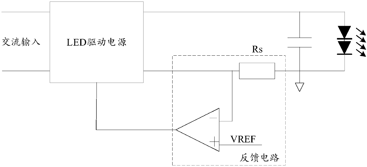
Although the latter can better eliminate the power frequency ripple of the output current, there will be a problem that the peak current reference will have a large error as the dimming depth is strengthened, so that the driving power cannot achieve a wide enough dimming range.
Therefore, the existing dimming technology cannot better meet the dimming requirements of wide dimming range and low output current ripple

Method used


Image

  • Multi-mode current control method and dimming circuit
  • Multi-mode current control method and dimming circuit
  • Multi-mode current control method and dimming circuit

Examples


Embodiment Construction

[0033] Example embodiments will now be described more fully with reference to the accompanying drawings. Example embodiments may, however, be embodied in many forms and should not be construed as limited to the examples set forth herein; rather, these embodiments are provided so that this disclosure will be thorough and complete and will fully convey the concept of example embodiments to those skilled in the art. The described features, structures, or characteristics may be combined in any suitable manner in one or more embodiments. In the following description, numerous specific details are provided in order to give a thorough understanding of embodiments of the present disclosure. However, those skilled in the art will appreciate that the technical solutions of the present disclosure may be practiced without one or more of the specific details being omitted, or other methods, components, devices, steps, etc. may be adopted. In other instances, well-known technical solution...


PUM


Abstract

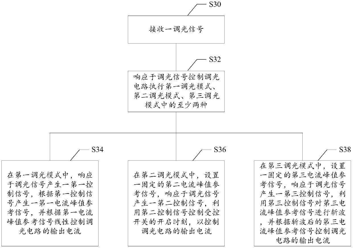
The invention discloses a multi-mode current control method and a dimming circuit and relates to the technical field of illumination. The multi-mode current control method comprises steps that a dimming signal is received, in response to the dimming signal, the dimming circuit is controlled for operating in various modes in any sequence, wherein the multiple modes comprise any two or all of a first dimming mode, a second dimming mode and a third dimming mode, and the dimming circuit can have different mode combinations according to actual requirements, and thereby the dimming requirements of awide dimming range and low output current ripples can be met.

Description

technical field [0001] The present disclosure relates to the technical field of lighting, in particular, to a multi-mode current control method and a dimming circuit. Background technique [0002] For occasions such as stadiums, it is necessary to use high-speed cameras for on-site broadcast or lens playback. In this process, lighting equipment plays an indispensable role. Especially when a high-speed camera is performing slow-motion playback, it is necessary to achieve, for example, 1000 frames per second without flickering, which requires that the driving circuit must have very low ripple, and in order to meet the needs of different lighting brightness, the driving circuit needs to be wide enough. dimming range. [0003] At present, LED (Light Emitting Diode, light-emitting diode) driving power usually adopts secondary side feedback or peak current control method for dimming. The former will introduce power frequency ripple, and due to the problem of sampling resistor acc...

Claims


Application Information

Patent Timeline
Patent Type & Authority Applications(China)
IPC IPC(8): H05B33/08H05B44/00
CPCH05B45/14H05B45/37H05B45/10
Inventor 吴缺傅小平郑凯斌章兴华
Owner DELTA ELECTRONICS INC
Learn More