Glass auxiliary edge removing equipment for building decoration

A glass and architectural technology, applied in the field of auxiliary glass edge removal equipment for architectural decoration, can solve the problems of easy deviation, uneven installation size, uneven glass, etc., and achieve the effect of easy measurement, easy operation, and simple structure

Active Publication Date: 2019-12-24
江苏远工建设有限公司
View PDF8 Cites 4 Cited by
  • Summary
  • Abstract
  • Description
  • Claims
  • Application Information

AI Technical Summary

Problems solved by technology

[0003] In building decoration, glass plates are frequently used plates. During the installation process, due to the different installation sizes, it is often necessary to measure and remove the edge of the glass plate. Due to the problem of glass material, it is not often processed with a cutting knife. Personnel use a sliding knife to draw a line, and then break it directly, and manually draw the line, which is prone to deviation and causes the glass to be uneven

Method used


Image

  • Glass auxiliary edge removing equipment for building decoration
  • Glass auxiliary edge removing equipment for building decoration
  • Glass auxiliary edge removing equipment for building decoration

Examples


Embodiment 1

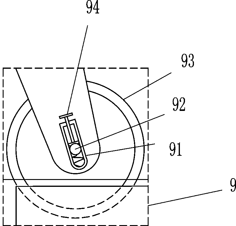
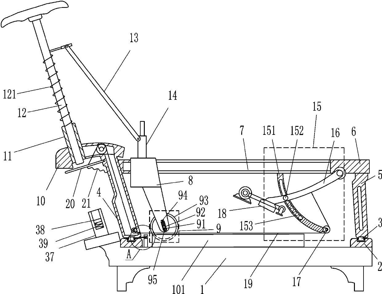
[0019] like Figure 1-3 As shown, a glass auxiliary edge removal device for building decoration includes a base 1, a baffle plate 101, a straight slide rail 2, a straight slide block 3, a first mounting frame 4, a second mounting frame 5, a mounting plate 6, a sliding Block 8, cutting device 9, installation sleeve 10, guide sleeve 11, pressure rod 12, first elastic member 121, connecting rod 13, installation block 14, guide mechanism 15, first swing rod 16, guide wheel 17, pressure block 18 , pull cord 19, second swing lever 20 and third elastic member 21, a baffle plate 101 is arranged on the front side of the top of the base 1, a straight slide rail 2 is arranged symmetrically on the left and right sides of the top of the base 1, and a straight slide rail 2 is slidably arranged on the straight slide rail 2. Slider 3, the straight slider 3 on the left side is provided with the first installation frame 4, and the first installation frame 4 has inner cavity, and the straight sl...

Embodiment 2

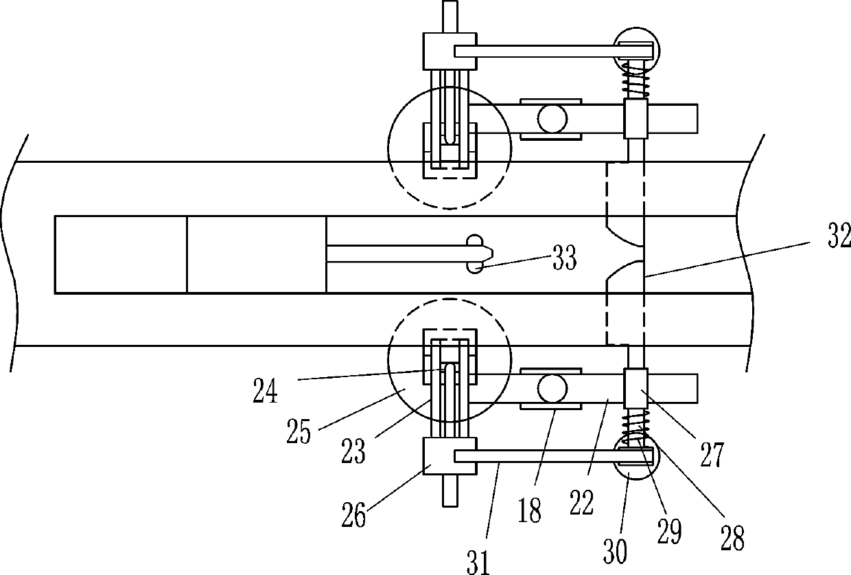
[0024] like Figure 1-3 As shown, on the basis of Embodiment 1, it also includes a fixed rod 22, a straight slide rail 23, a straight slide block 24, a first suction cup 25, a connecting block 26, a guide sleeve 27, a guide rod 28, and a fourth elastic member 29 , the second suction cup 30, connecting rod 31, wedge block 32 and top block 33, the first swing rod 16 lower side is provided with a fixed rod 22, the left side of the fixed rod 22 is provided with a straight slide rail 23, sliding on the straight slide rail 23 The straight-running slider 24 is provided with a straight-running slider 24, the bottom of the straight-running slider 24 is provided with a first sucker 25, the top of the straight-running slider 24 is provided with a connecting block 26, the right side of the fixed rod 22 is provided with a guide sleeve 27, and the movable type in the guide sleeve 27 is provided with Guide rod 28, the fourth elastic member 29 is arranged between the guide rod 28 and the guid...


PUM


Abstract

The invention belongs to the technical field of decoration equipment, and particularly relates to glass auxiliary edge removing equipment for building decoration. The glass auxiliary edge removing equipment for building decoration aims at achieving the technical purposes of being convenient to slide, easy to measure and capable of assisting in breaking apart. The glass auxiliary edge removing equipment comprises a base, a baffle, a straight sliding rail, a straight sliding block, a first mounting frame, a second mounting frame, a mounting plate, a sliding block, a cutting device, a mounting sleeve, a guide sleeve and the like. The baffle is arranged on the front side of the top of the base, the straight sliding rails are bilaterally symmetrically arranged on the top of the base, and the straight sliding blocks are slidably arranged on the straight sliding rails. The equipment achieves the effects of being convenient to slide, easy to measure and capable of assisting in breaking apart.

Description

technical field [0001] The invention belongs to the technical field of decoration equipment, and in particular relates to glass auxiliary edge-removing equipment for building decoration. Background technique [0002] With the development of modern science and technology and glass technology and the improvement of people's living standards, the function of architectural glass is no longer just to meet the lighting requirements, but to have the ability to adjust light, heat insulation, safety (bulletproof, anti-theft, fireproof, radiation, anti-electromagnetic interference), art decoration and other characteristics. With the continuous development of demand, glass molding and processing methods have also undergone new developments. Now, new technology glasses such as interlayer, tempering, ion exchange, glaze decoration, chemical thermal decomposition and cathode sputtering have been developed, so that the amount of glass used in buildings has increased rapidly, and it has be...

Claims


Application Information

Patent Timeline
Patent Type & Authority Applications(China)
IPC IPC(8): C03B33/033C03B33/027C03B33/03C03B33/12
CPCC03B33/027C03B33/03C03B33/033C03B33/12
Inventor 不公告发明人
Owner 江苏远工建设有限公司
Why Eureka
Try Eureka