
Tin-plated copper terminal material, terminal and wire end structure

A tinned copper and terminal technology, applied in the direction of circuits, contact parts, conductive materials, etc., can solve the problems of poor productivity, low durability, poor adhesion between the anti-corrosion layer and Sn plating, etc.

Active Publication Date: 2022-02-01
MITSUBISHI MATERIALS CORP
View PDF7 Cites 0 Cited by
  • Summary
  • Abstract
  • Description
  • Claims
  • Application Information

AI Technical Summary

Problems solved by technology

[0012] As in Patent Document 1, when the base of the tin layer is provided with an anti-corrosion layer made of zinc or zinc alloy, there is a problem that the anti-corrosion layer and the Sn-plated layer are caused by Sn substitution when the Sn plating process is carried out on the anti-corrosion layer. problems such as poor adhesion
[0013] As shown in Patent Document 2, when a Sn-containing 3 o 2 (OH) 2 In the case of a conductive film layer of (oxyhydroxide), there is a problem of low durability because the conductive film layer is rapidly damaged when exposed to a corrosive environment or a heating environment.
Furthermore, as shown in Patent Document 3, regarding a Sn-Zn alloy (surface Sn plating layer) laminated on a Sn-Cu-based alloy layer (intermediate Sn-Cu plating layer) and a Zn high-concentration layer on the outermost layer, Sn plating material, there is a problem that the productivity of the Sn-Zn alloy layer is poor and the corrosion protection effect on the aluminum wire disappears when the copper of the Sn-Cu alloy layer is exposed on the surface.

Method used


Image

  • Tin-plated copper terminal material, terminal and wire end structure
  • Tin-plated copper terminal material, terminal and wire end structure
  • Tin-plated copper terminal material, terminal and wire end structure

Examples


Embodiment

[0072]A copper plate of C1020 (oxygen-free copper) is used as the base material, and after degreasing and pickling, nickel plating or nickel alloy plating (only for samples 13 to 16 and 18) to form the base layer is sequentially performed, and an intermediate zinc layer is formed. The galvanized treatment or galvanized alloy treatment (except sample 17), the tin layer (tin alloy treatment or) tin-plated treatment, to prepare samples 1 to 19. The conditions of the main plating treatment performed on each sample are as follows.

[0073] The zinc content of the intermediate zinc layer is adjusted by changing the ratio of zinc ions in the zinc alloy plating solution to the added alloy element ions. For example, the following nickel-zinc alloy plating treatment conditions are an example in which the zinc concentration in the intermediate zinc layer is 85% by mass (sample 15).

[0074] The sample 17 was not subjected to any one of the nickel plating treatment, the zinc plating trea...


PUM

PropertyMeasurementUnit
thicknessaaaaaaaaaa
corrosion potentialaaaaaaaaaa
thicknessaaaaaaaaaa

Abstract

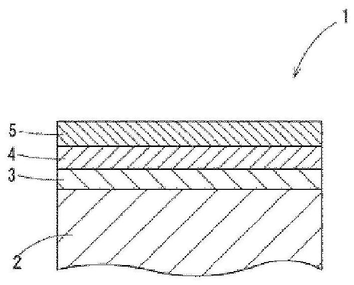
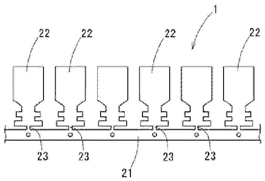
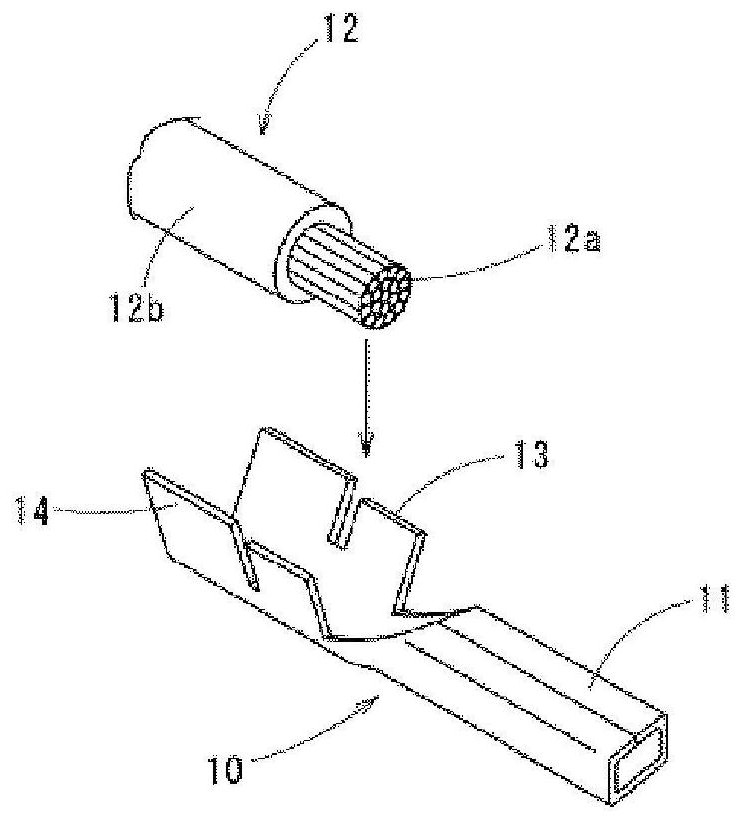
The present invention provides a tinned copper terminal material, a terminal made of the terminal material, and an electric wire end structure using the terminal. The tinned copper terminal material has: a base material, which is made of copper or a copper alloy; an intermediate zinc layer, formed on the base material and composed of a zinc alloy, and having a thickness of 0.10 μm or more and 5.00 μm or less; and a tin layer formed on the intermediate zinc layer and composed of tin or a tin alloy, and having a small-tilt grain boundary length The tin-plated copper terminal material effectively suppresses galvanic corrosion when the ratio to the total grain boundary length is 2% or more and 30% or less.

Description

technical field [0001] The present invention relates to a tin-plated copper terminal material, a terminal made of the terminal material, and an electric wire terminal structure using the terminal. [0002] This application claims priority based on Japanese Patent Application No. 2017-096979 filed on May 16, 2017, and uses the content thereof here. Background technique [0003] Conventionally, the lead wire is connected to the other device by connecting the terminal crimped to the terminal portion of the lead wire to a terminal provided on the other device. Lead wires and terminals are generally formed of highly conductive copper or copper alloys, but lead wires made of aluminum or aluminum alloys are also used for weight reduction and the like. [0004] For example, Patent Document 1 discloses an electric wire with a terminal in which a terminal made of copper (copper alloy) on which a tin-plated layer is formed is crimped to a lead wire made of aluminum or an aluminum allo...

Claims


Application Information

Patent Timeline
Patent Type & Authority Patents(China)
IPC IPC(8): C25D7/00C22C18/00C25D5/10C25D5/12C25D5/50H01R4/18H01R4/62H01R13/03
CPCH01R4/62H01R13/03C22C18/00C25D5/12C25D7/00C25D3/12C25D3/565C25D5/10C25D3/30H01R4/185C25D5/617H01R4/18Y10T428/12715B32B2255/205C22C13/00Y10T428/12708H01B1/026B32B15/20B32B2255/06B32B2250/03
Inventor 久保田贤治樽谷圭荣中矢清隆
Owner MITSUBISHI MATERIALS CORP
Learn More