Strip steel uncoiling mechanism

A strip steel and chassis technology, applied in the field of strip steel uncoiling mechanism, can solve problems affecting strip steel uncoiling, coil strip steel loosening, coil strip steel slipping, etc., to achieve loosening prevention, firm and stable structure, and good load bearing effect Effect

Inactive Publication Date: 2019-12-20
武汉宏升鑫汽车部件有限公司
View PDF6 Cites 2 Cited by
  • Summary
  • Abstract
  • Description
  • Claims
  • Application Information

AI Technical Summary

Problems solved by technology

[0004] The above-mentioned existing technical solutions have the following defects: in the process of strip steel uncoiling, as the strip steel is gradually unrolled and transported away, the coiled steel strip installed on the expansion shoe will become less and less, because the strip steel It has a certain degree of elasticity, so the coiled steel strip will become looser and looser, so the remaining coiled steel strip is likely to slip due to looseness, which will affect the normal uncoiling of the strip steel, so it needs to be improved

Method used


Image

  • Strip steel uncoiling mechanism
  • Strip steel uncoiling mechanism
  • Strip steel uncoiling mechanism

Examples


Embodiment 1

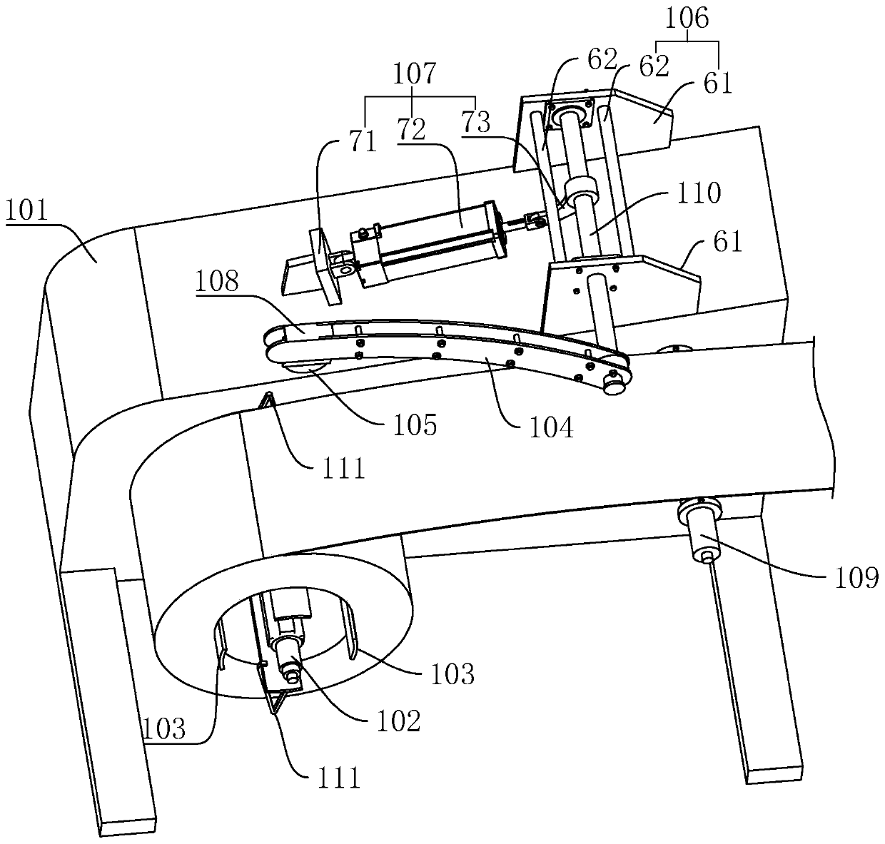
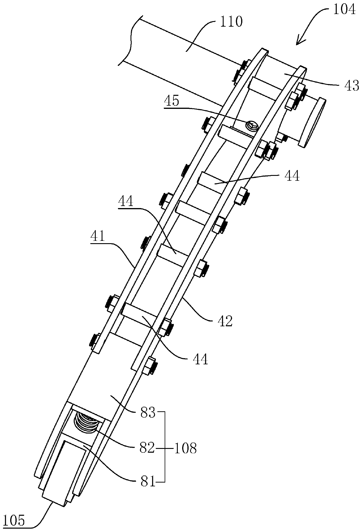
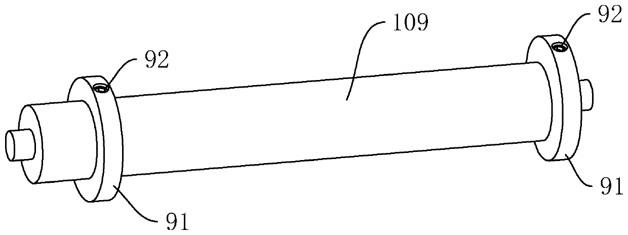
[0035] refer to figure 1, is a strip uncoiling mechanism disclosed in the present invention, comprising: a chassis 101, a power motor, an uncoiling spindle 102, a tension shoe 103, a guide roller 109, a rotating shaft 110, an arc arm 104, a pressure wheel 105, and a mounting frame 106 , the driving member 107 and the elastic component 108, the power motor is arranged in the cabinet 101, the unwinding main shaft 102 is rotated and arranged on one side of the cabinet 101, the power motor drives the unwinding main shaft 102 to rotate, and the unwinding main shaft 102 is provided with four expansion pads 103, The coiled steel strip is sheathed on the expansion shoe 103 .

[0036] Mounting frame 106 is installed on the top surface of cabinet 101, and guide roller 109 is located at the side of cabinet 101 and is positioned at the oblique top of unwinding main shaft 102, and rotation shaft 110 is arranged on the mounting frame 106 and is positioned at the top of guiding roller 109, u...

Embodiment 2

[0046] refer to Figure 4 , is a strip steel uncoiling mechanism disclosed in the present invention. The difference from Embodiment 1 is that the driving member 107 includes: a servo motor 74 and a reduction box 75, and the servo motor 74 and the reduction box 75 are installed on the cabinet 101 to reduce the speed. The box 75 is connected between the output shaft of the servo motor 74 and the rotation shaft 110 . The servo motor 74 can very precisely control the forward and reverse rotation of its output shaft, and then reduce the speed of the output shaft of the servo motor 74 through the reduction box 75, and then drive the rotating shaft 110 to rotate. The structure of the driving member 107 of the above design is simple, Easy to operate.


PUM


Abstract

The invention relates to a strip steel uncoiling mechanism, and relates to the technical field of production of metal stamping parts. The strip steel uncoiling mechanism comprises a machine case, a power motor, an uncoiling spindle and an expansion tile, and further includes a guide roller, a rotating shaft, an arc arm, a pressure wheel, a mounting frame, a driving part and an elastic component; the mounting frame is installed on the top surface of the machine case, the guide roller is arranged on the side face of the machine case and is located obliquely above the uncoiling spindle, the rotating shaft is rotatably arranged on the mounting frame and located above the guide roller, and the uncoiling spindle, the guide roller and the rotating shaft are arranged horizontally and are arrangedin parallel; the driving part is arranged between the machine case and the rotating shaft, the driving part is used for driving the rotating shaft to rotate forwards and backwards, one end of the arcarm is connected to the rotating shaft, and the other end of the arc arm is provided with the elastic component; and the pressure wheel is rotatably arranged on the elastic component, the rotation axis of the pressure wheel is parallel to the uncoiling spindle, and the elastic component is used for driving the pressure wheel to press the upper surface of strip steel. The strip steel uncoiling mechanism has the effects of being stable and firm in structure and being capable of pressing the rolled strip steel on the expansion tile to prevent the rolled strip steel from loosening.

Description

technical field [0001] The invention relates to the technical field of metal stamping parts production, in particular to a strip uncoiling mechanism. Background technique [0002] Metal stamping parts are generally widely used in all walks of life, especially in the automotive industry. Many accessories are stamped from metal sheets. Metal sheets are generally rolled into rolls (referred to as coiled strips) for transportation. When producing metal stamping parts , It is necessary to use an uncoiler to stretch the rolled strip steel, then pass through a leveler for leveling treatment, and then enter the stamping machine for stamping and forming to obtain metal stamping parts. [0003] A Chinese utility model patent with a notification number of CN203390052U has been retrieved, which discloses a corrugated plate production line, which includes a cantilever uncoiler, a leveling machine, a cold roll forming machine and a punching and cutting machine arranged in sequence from fr...

Claims


Application Information

Patent Timeline
Patent Type & Authority Applications(China)
IPC IPC(8): B21C47/18B21C47/26B21C47/32
CPCB21C47/18B21C47/26B21C47/326
Inventor 张勇
Owner 武汉宏升鑫汽车部件有限公司
Why Eureka
Try Eureka