
Low-pair multi-rod mechanism spheronization machine

A technology of multi-rod mechanism and rounding machine, which is applied in the field of steel rolling, can solve the problems of poor dimensional accuracy, unbalanced load burning of rolling mill bearings, difficulty in ensuring the turning accuracy of roll grooves, etc., and achieve the elimination of processing and assembly errors, radial contact, etc. The effect of large area and compact structure layout

Pending Publication Date: 2019-12-20
SHANDONG IRON & STEEL CO LTD
View PDF0 Cites 0 Cited by
  • Summary
  • Abstract
  • Description
  • Claims
  • Application Information

AI Technical Summary

Problems solved by technology

[0006] In the prior art, eccentric grooves are generally installed directly on the rolls of the rolling mill. Due to the large moment of inertia of the eccentric rolling of the rolls, it is easy to cause local eccentric load burning of the bearings of the rolling mill, and the machining and manufacturing of the eccentric grooves is difficult, so it is difficult to ensure the turning of the grooves. Accuracy, resulting in poor controllable dimensional accuracy of the appearance of the rolled material and high cost
In the prior art, there are also mechanisms that use external equipment to control the rounding of the rolls, but these mechanisms have the disadvantages of high cost, large floor space, complicated control, and the inability to adjust the range of motion of the rolls according to the actual situation and the adjustment is not accurate enough

Method used


Image

  • Low-pair multi-rod mechanism spheronization machine
  • Low-pair multi-rod mechanism spheronization machine
  • Low-pair multi-rod mechanism spheronization machine

Examples


Embodiment Construction

[0055] The present invention will be described in detail below with reference to the accompanying drawings and examples. Each example is provided by way of explanation of the invention, not limitation of the invention. In fact, it will be apparent to those skilled in the art that modifications and variations can be made in the present invention without departing from the scope or spirit of the invention. For example, features illustrated or described as part of one embodiment can be used on another embodiment to yield a still further embodiment. Therefore, it is intended that the present invention includes such modifications and variations as come within the scope of the appended claims and their equivalents.

[0056] In the description of the present invention, the terms "longitudinal", "transverse", "upper", "lower", "front", "rear", "left", "right", "vertical", "horizontal", " The orientations or positional relationships indicated by "top", "bottom", etc. are based on the...


PUM


Abstract

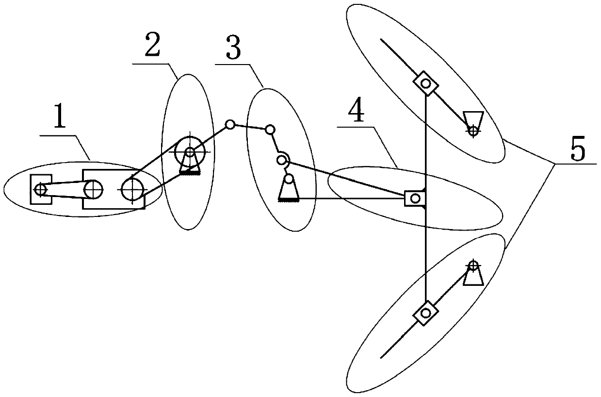
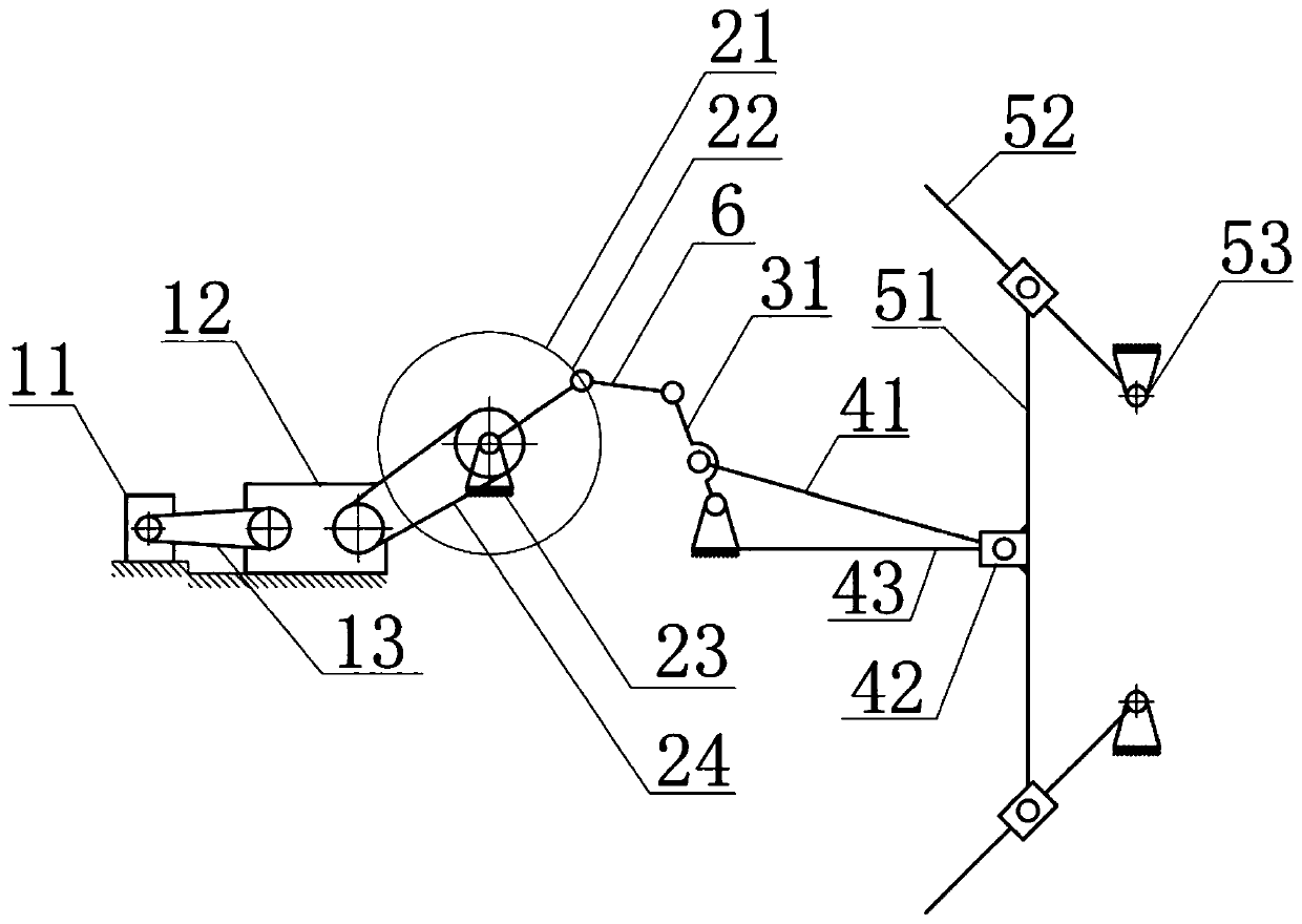
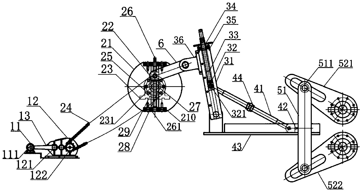
The invention provides a low-pair multi-rod mechanism spheronization machine. The spheronization machine includes a power mechanism, an eccentric mechanism, a rocker arm mechanism, a traverse moving mechanism and a swing angle mechanism. The power mechanism is used for providing power; the eccentric mechanism is arranged on the downstream of the power mechanism and is used for converting the powerof the power mechanism into rotary motion and then transferring the rotary motion to the rocker arm mechanism; the rocker arm mechanism is located on the downstream of the eccentric mechanism, performs rocking motion under the action of the eccentric mechanism and simultaneously drives the traverse moving mechanism to move; the traverse moving mechanism is arranged on the downstream of the rockerarm mechanism, and the traverse moving mechanism can drive the swing angle mechanism to move while moving; and the swing angle mechanism is also connected to upper and lower rollers of a rolling milland is used for driving the upper and lower rollers to perform synchronous reverse circular rotation swing. The low-pair multi-rod mechanism spheronization machine can be matched and connected with rollers of different rolling mills through shaft sleeves to drive the rollers to perform reciprocating rounding motion, the significant characteristics of the small size, the light weight, the compactlayout structure, the large transmission power and the high adjustment accuracy are achieved, and the low-pair multi-rod mechanism spheronization machine is especially suitable for small-specificationbar products.

Description

technical field [0001] The invention relates to the technical field of steel rolling, in particular to a rounding machine with a low pair of multi-rod mechanism. Background technique [0002] "Hot-rolled ribbed steel bars for anchor rods" belongs to a large category of bar products, which are widely used in rock and soil support projects in coal mines and other mine roadways and tunnels. "Steel bars" are widely used, and the market demand around Shandong is about 400,000 tons per year, and the market prospect is broad. [0003] During the use of "crescent rib anchor steel bars", coal mine users often cut the purchased "double-scale anchor steel finished products" to length according to the actual needs of the site, and cut them into semi-finished products with a length of about 1800mm-2200mm , and then carry out the overall "cold pressure rounding" treatment on the outer surface of the local range of about 300mm from the end face of the "cut-to-length material" to eliminate...

Claims


Application Information

Patent Timeline
IPC IPC(8): B21B1/16B21B15/00
CPCB21B1/16B21B15/00
Inventor 李永峰王建伟王莉李来中杨平李道峰亓敏
Owner SHANDONG IRON & STEEL CO LTD
Learn More