FPM-based micro imaging system

A technology for microscopic imaging and imaging objects, used in microscopes, optics, instruments, etc., can solve the problems of low energy, low signal-to-noise ratio, and small field of view, and achieve high illumination energy, reduced signal-to-noise ratio, and wide field of view. Effect

Inactive Publication Date: 2019-12-13
TSINGHUA UNIV
View PDF10 Cites 6 Cited by
  • Summary
  • Abstract
  • Description
  • Claims
  • Application Information

AI Technical Summary

Problems solved by technology

[0003] However, the existing FPM-based microscopic illumination system generally uses LED as the light source, which has the characteristics of small field of view, low energy, and low signal-to-noise ratio.
There is still a contradiction between the number of openings of digital micromirrors and the signal-to-noise ratio and resolution in the microscopic illumination system using laser light source

Method used


Image

  • FPM-based micro imaging system

Examples


Embodiment Construction

[0021] Embodiments of the present invention are described in detail below, examples of which are shown in the drawings, wherein the same or similar reference numerals designate the same or similar elements or elements having the same or similar functions throughout. The embodiments described below by referring to the figures are exemplary and are intended to explain the present invention and should not be construed as limiting the present invention.

[0022] The FPM-based microscopic imaging system proposed according to an embodiment of the present invention is described below with reference to the accompanying drawings

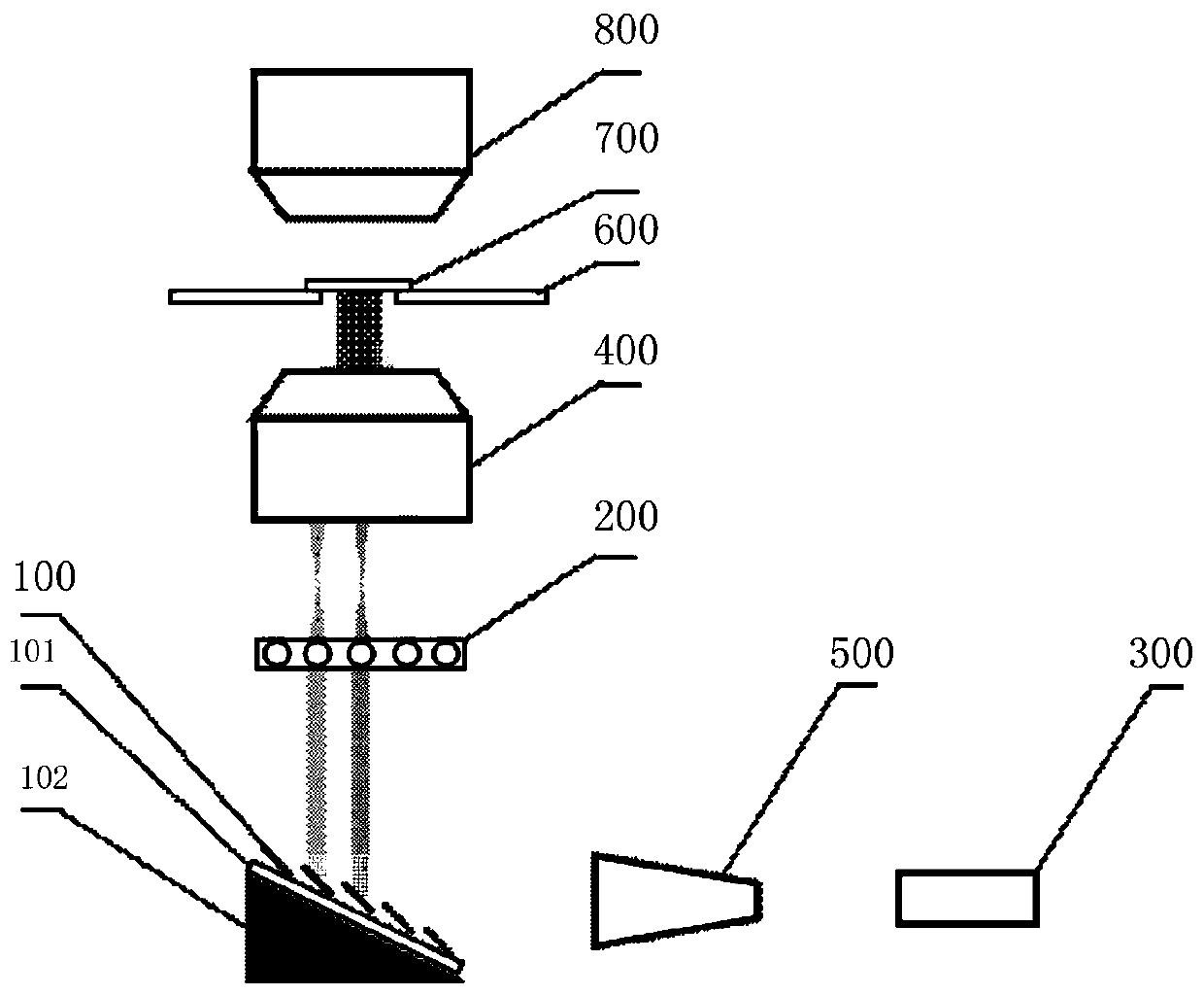
[0023] figure 1 It is a schematic structural diagram of an FPM-based microscopic imaging system according to an embodiment of the present invention.

[0024] Such as figure 1 As shown, the FPM-based microscopic imaging system includes: a digital micromirror 100 , a microlens array 200 , a laser 300 and an illumination objective lens 400 .

[0025] Wherein,...


PUM


Abstract

The invention discloses an FPM-based micro imaging system. The system comprises a digital micro mirror, a micro lens array, a laser used for emitting light to the digital micro mirror for enabling thedigital micro mirror to reflect the light to the lens array, and an illumination objective lens used for converting spherical waves into plane waves after the micro lens array converts the plane waves into the spherical waves and transmits the light to the illumination objective lens, and irradiating the light to an imaging object placed on an object carrying hole to perform imaging. According tothe system, a to-be-tested sample can be illuminated at different angles by cooperation of the digital micro mirror and the micro lens array; an imaging instrument obtains a low-resolution image; andthen an FPM algorithm is used for iterative reconstruction, so that the image resolution is improved and is equivalent to the resolution of the high-power objective lens, the wider field of view is achieved, the energy of the system is improved, the signal-to-noise ratio is reduced, and the imaging speed is improved.

Description

technical field [0001] The invention relates to the technical field of microscopic imaging, in particular to an FPM-based microscopic imaging system. Background technique [0002] In related technologies, due to the limitation of the space-bandwidth product of the optical microscope itself, its information flux is certain. To obtain high-resolution images, the numerical aperture must be increased, but the field of view is limited. FPM (FourierPtychography Microscopy, frequency-domain stacked microscope) can bypass the resolution limit of the objective lens, greatly improve the spatial bandwidth product of the system, and enable the objective lens with a small numerical aperture to obtain higher frequency information, which can only obtain low-frequency information. Directional light to improve resolution. [0003] However, the existing FPM-based microscopic illumination systems generally use LEDs as light sources, which have the characteristics of small field of view, low ...

Claims


Application Information

Patent Timeline
Patent Type & Authority Applications(China)
IPC IPC(8): G02B21/06G02B21/36
CPCG02B21/06G02B21/361G02B21/365
Inventor 戴琼海张雅琳范静涛
Owner TSINGHUA UNIV
Why Eureka
Try Eureka