Collision protection method

A technology of collision object and speed direction, applied in the field of driving or reducing damage, it can solve the problems of large collision mass and large traveling speed.

Active Publication Date: 2019-12-13
AGIE CHARMILLES
View PDF12 Cites 0 Cited by
  • Summary
  • Abstract
  • Description
  • Claims
  • Application Information

AI Technical Summary

Problems solved by technology

[0006] With these known methods of reaction, the damage experienced can still be significant because the machine tool is built to be rigid such that the collision mass is usually quite large and the travel speed can also be considerable

Method used


Image

  • Collision protection method
  • Collision protection method
  • Collision protection method

Examples


Embodiment Construction

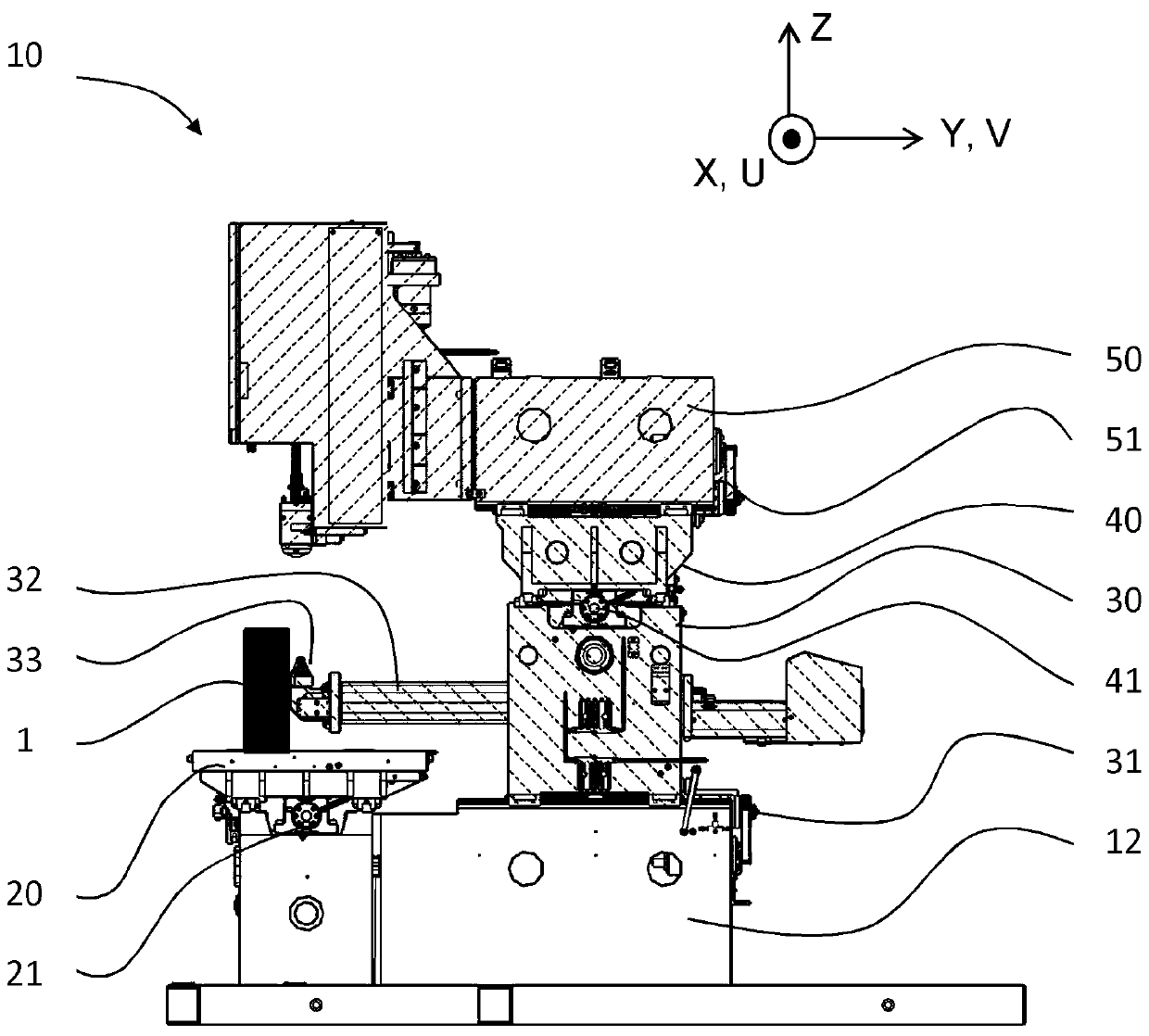
[0133] In a wire electrical discharge machine (WEDM), a tool (ie, a tensioned traveling wire electrode) is guided above and below the workpiece. Basically, the upper and lower wire guides move in two parallel planes above and below the workpiece by means of X / Y and U / V axis pairs, and the vertical Z axis is used to control the two wire guides distance between pieces. The wire guide is used to precisely guide the tensioned running wire electrode. The wire guides move independently in the two planes to perform cylindrical or conical machining of the workpiece.

[0134] In general, the nomenclature of axes in machine tools is defined by ISO 841 "Industrial automation systems and integration - Numerical control of machines - Nomenclature of coordinate systems and motion", where X, Y and Z are linear axes, where Z is related to the machine's The spindle (or tool) is aligned; A, B, and C are rotational axes about X, Y, and Z, respectively; and U, V, and W are parallel linear axes ...


PUM


Abstract

The present invention is directed to a method for mitigation of the damages in case of accidental collisions in a machine tool comprising a computer numerical control (CNC) and a plurality of axes, wherein the occurrence of collisions is monitored, comprises: identifying a first axis being an axis at which a collision is first detected, identifying a second axis being an axis parallel to said first axis, and determining if both or one or none of the axes are resting. If both are resting unlocking the first axis or both axes. If the first axis or second axis is not resting, then the moving axisis defined as the collider, and said moving axis is broken, and simultaneously the resting axis is unlocked or stepped away or held in position. If both axes are moving, defining a collider axis based on said identified first axis at which a collision has been first detected, braking said collider axis and simultaneously unlocking or stepping away the axis parallel to said collider axis.

Description

Background technique [0001] The present invention discloses a method of mitigating damage in the event of an accidental collision with a machine tool, especially a wire electrical discharge machine. [0002] A problem with machine tools, manipulators and other devices with one or more positioning axes is the risk of accidental collisions, ie between parts of the machine and other machine parts or workpieces or clamping tools or other parts. A crash can determine significant damage to the machine and interruption of operation. Several active, passive, preventive and reactive protection methods and devices have thus been developed and are known in the art. The present invention discloses a reactive method in which a crash event is detected and appropriate action is taken to avoid or limit damage. [0003] It is known in the art to perform emergency braking when a collision event is detected. Emergency braking is performed by commutating the motor current to the maximum possib...

Claims


Application Information

Patent Timeline
Patent Type & Authority Applications(China)
IPC IPC(8): B23H7/02B23H11/00
CPCB23H7/02B23H11/00G05B19/4061G05B2219/37624G05B2219/45043G05B2219/49147G05B9/02G05B19/19G05B2219/37237G05B2219/37622G05B2219/37629
Inventor M.塔博瑞利
Owner AGIE CHARMILLES
Why Eureka
Try Eureka