
Hydraulic actuators, control valves and main valves of control valves

A technology for hydraulically operating and controlling valves, which is applied to engine components, fluid pressure actuators, multi-way valves, etc., and can solve problems such as manual operation of the spool

Active Publication Date: 2021-07-02
PINGGAO GRP +2
View PDF4 Cites 0 Cited by
  • Summary
  • Abstract
  • Description
  • Claims
  • Application Information

AI Technical Summary

Problems solved by technology

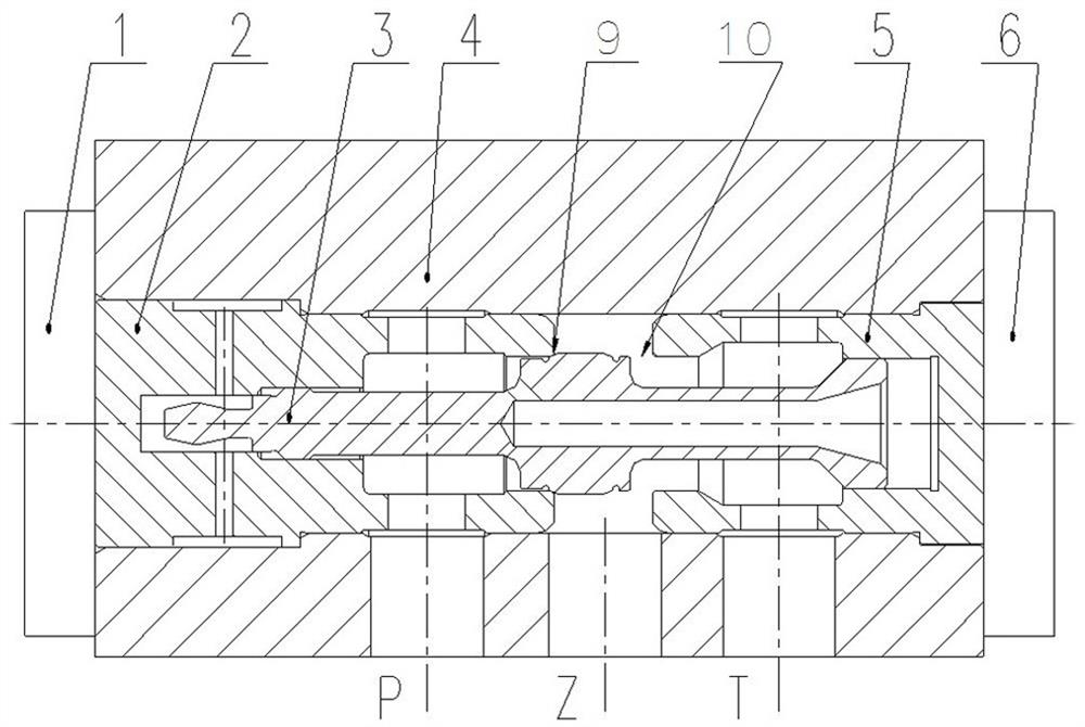
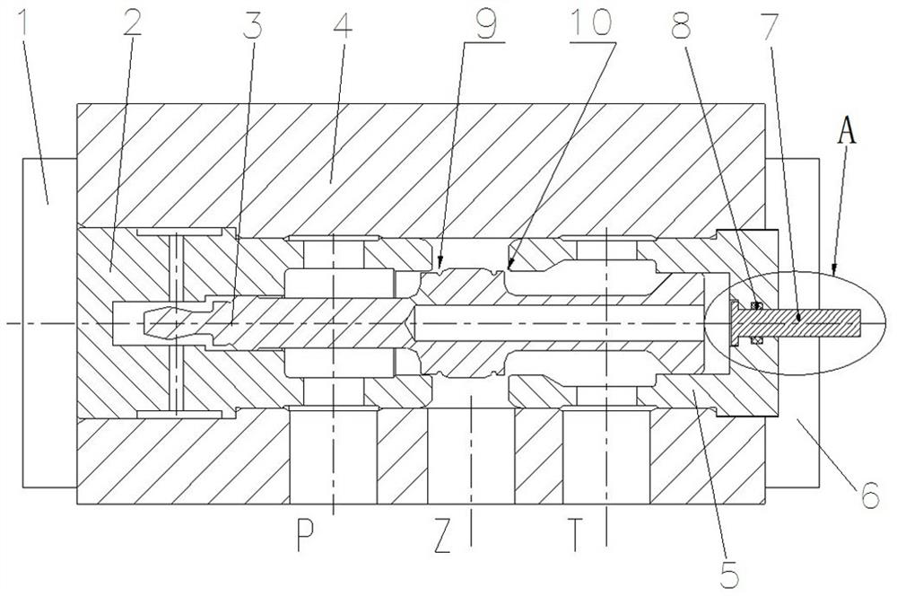
[0005] The purpose of the present invention is to provide a control valve with manual operation function to solve the problem that the existing control valve cannot manually operate the valve core; the purpose of the present invention is also to provide a hydraulic control valve using the control valve. actuator and the main valve of the control valve

Method used


Image

  • Hydraulic actuators, control valves and main valves of control valves
  • Hydraulic actuators, control valves and main valves of control valves
  • Hydraulic actuators, control valves and main valves of control valves

Examples


Embodiment 2

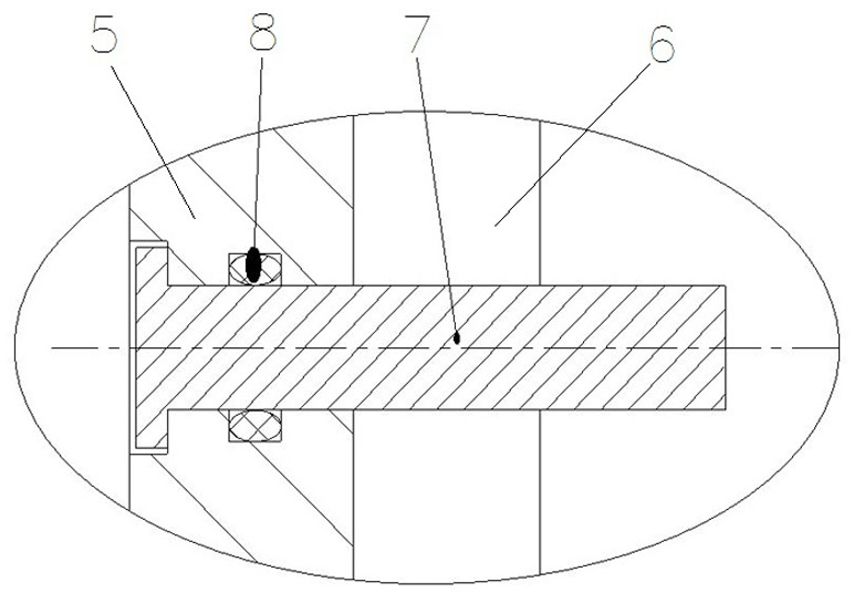
[0036] Embodiment 2 The second embodiment is different from the first embodiment in that the main valve of the control valve does not include the operating lever, the operating lever is additionally provided; the control valve is blocked when the valve is worked, such as a screw, and the main valve valve body The end of the operating lever is blocked; when the maintenance is required, the sealing member is removed and the operating lever is introduced into the operating lever perforation.

Embodiment 3

[0037] Example III, Embodiment 3 Examples An Example One is in that one end of the operating member is connected by a threaded structure and a main valve valve core; when the main valve spool is not in place, drive or pull the operating rod to drive Main valve spool action.

Embodiment 4

[0038] Example 4, Example 4 Example 4 Different Embodiment An Spring of the operating rod and the main valve body is provided to apply a reset force to the operating lever, after the manual operation is completed, the operating rod is in the spring force Automatically reset automatically.


PUM


Abstract

The invention relates to a hydraulic operating mechanism, a control valve and a main valve of the control valve. The control valve includes a main valve and a secondary valve arranged on the main valve. The main valve includes a main valve body and is slidably arranged in the main valve body. The main valve spool of the main valve body is provided with an operating rod perforation for the operating rod to pass through to drive the main valve spool to move at the position corresponding to the end of the main valve spool; the main The valve also includes a blocking member for blocking the perforation of the operating rod. In case of improper operation, the movement of the main valve spool is not in place, and the valve ports of the two main valves are not sealed, remove the blocking parts, open the perforation of the operating rod, insert the operating rod into the main valve, and be driven by the operating rod. The spool of the main valve moves to seal the main valve port on one side, so that the system can re-store energy. In this way, when the control valve is maintained, it is not necessary to remove the control valve from the mechanism, avoiding oil draining, oil filling, wire connection, cleaning, etc., and greatly improving work efficiency.

Description

Technical field [0001] The present invention relates to a control valve having a manual operating function, a main valve of the control valve and a hydraulic actuator using the control valve. Background technique [0002] The electromagnetic control valve is the core component of the hydraulic operation mechanism, and is used to convert the separation or closing command electrical signal emitted by the control chamber into a hydraulic signal and enlarged, and control the actuation mechanism to perform a split, closing and automatic reclosing action. , Drive the broken circuit breaker body to achieve a handling, closing and automatic recrystal operation. The electromagnetic control valve currently used in the hydraulic operation mechanism is mainly two-bit three-way control valve, such as the release number of CN106783422A, which announced a hydraulic control valve disclosed in China's 2011.05.31 Chinese invention patent application. [0003] The control valve includes the main va...

Claims


Application Information

Patent Timeline
Patent Type & Authority Patents(China)
IPC IPC(8): F15B13/02F16K11/065F16K27/04F16K27/08
CPCF15B13/021F16K11/065F16K27/04F16K27/08
Inventor 李海文刘宇刘煜雷琴胡月萍王双盾
Owner PINGGAO GRP
Learn More