A film condensation method for gas dehumidification

A gas and wet gas technology, applied in the field of separation, can solve the problems of reduced heat recovery rate and water vapor recovery efficiency, and achieve the effects of avoiding reheating, increasing membrane penetration rate, and reducing pipeline corrosion

Active Publication Date: 2022-05-27
SOUTH UNIVERSITY OF SCIENCE AND TECHNOLOGY OF CHINA
View PDF7 Cites 0 Cited by
  • Summary
  • Abstract
  • Description
  • Claims
  • Application Information

AI Technical Summary

Problems solved by technology

[0008] The above method recovers the saturated water vapor in the flue gas by means of membrane separation, but as the recovery proceeds, the temperature difference between the flue gas side and the circulating water side gradually decreases, and the driving force of the condensed water from the flue gas side to the circulating water side If it is lowered, the recovery efficiency of water vapor in the flue gas will decrease, and the heat recovery rate will also decrease; therefore, it is of great significance to propose a membrane separation method that can maintain the water recovery rate for energy saving, emission reduction, and economic benefit improvement.

Method used


Image

  • A film condensation method for gas dehumidification
  • A film condensation method for gas dehumidification
  • A film condensation method for gas dehumidification

Examples


Embodiment 1

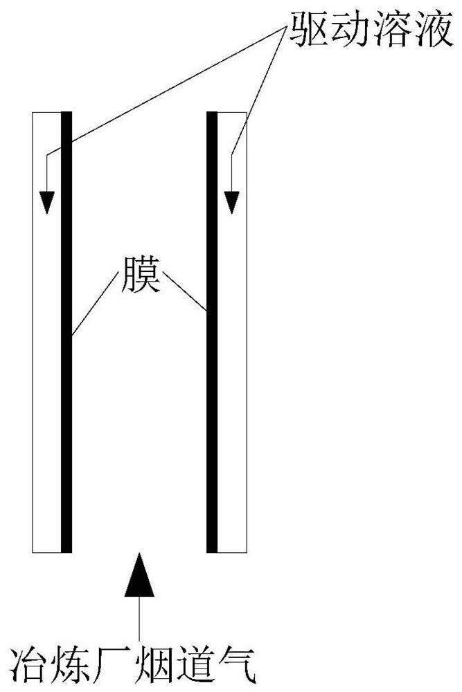
[0041] The present embodiment provides a membrane condensation method for dehumidifying flue gas in a smelter plant. The schematic flowchart of the membrane condensation method is as follows: figure 1 shown, including the following steps:

[0042] (1) The water vapor in the moisture-containing gas with a temperature of 200 °C and a relative humidity of 100% is condensed and transferred through the membrane, and the condensed water is recovered by the driving solution on the liquid side of the membrane; wherein, the moisture-containing gas and the driving solution flow in countercurrent , the flow rate of the membrane surface containing the wet gas is 1m / s, and the flow rate of the driving solution is 3m / s. The driving solution is a NaCl solution with a temperature of 16 ° C and a concentration of 1.5 mol / L; the wet gas is a smelter flue. gas;

[0043] (2) The driving solution after recovering the condensed water is concentrated to a KCl concentration of 1.5 mol / L by means of ...

Embodiment 2

[0045] The present embodiment provides a membrane condensation method for dehumidifying exhaust gas of a coal-fired power plant boiler after desulfurization, and the method includes the following steps:

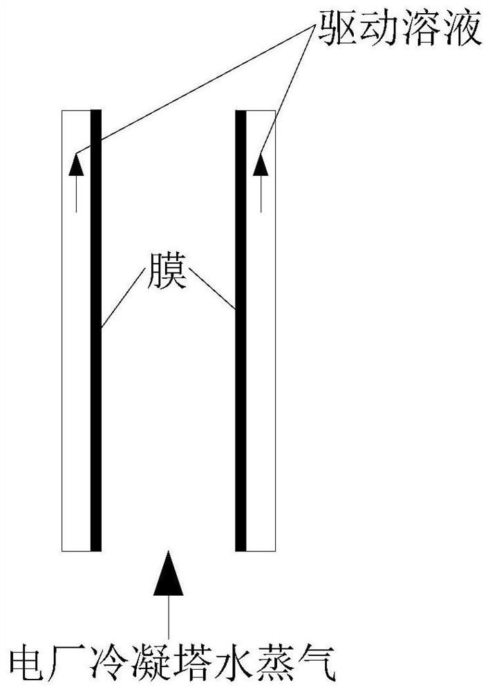
[0046] (1) The water vapor in the moisture-containing gas with a temperature of 80 °C and a relative humidity of 90% is condensed and transferred through the membrane, and the condensed water is recovered by the driving solution on the liquid side of the membrane; wherein the moisture-containing gas and the driving solution flow countercurrently , the flow rate of the membrane surface of the wet gas is 0.5m / s, the flow rate of the driving solution is 1m / s, and the driving solution is seawater with a temperature of 21 ° C; the wet gas is the desulfurized coal-fired power plant boiler exhaust;

[0047] (2) The driving solution after recovering the condensed water enters the reverse osmosis seawater desalination device to produce pure water, and the recovered water can be used as...

Embodiment 3

[0049] The present embodiment provides a film condensation method for dehumidifying boiler exhaust gas after reheating, and the method includes the following steps:

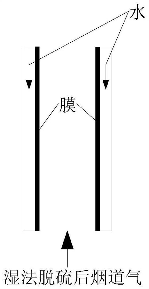
[0050] (1) The water vapor in the moisture-containing gas with a temperature of 150 °C and a relative humidity of 60% is condensed and transferred through the membrane, and the condensed water is recovered by the driving solution on the liquid side of the membrane; wherein the moisture-containing gas and the driving solution flow countercurrently , the flow rate of the membrane surface containing the wet gas is 2.5m / s, the flow rate of the driving solution is 5m / s, and the driving solution is seawater desalination reverse osmosis concentrated water with a temperature of 20 ° C; the wet gas is the reheated boiler exhaust gas ;

[0051] (2) The driving solution after recovering the condensed water is used as the reverse osmosis seawater desalination device to produce pure water after the heat is recovered by the he...


PUM


Abstract

The invention relates to a membrane condensation method for gas dehumidification. The membrane condensation method comprises the following steps: the water vapor in the wet gas is condensed and transferred through the membrane, and the driving solution on the liquid side of the membrane is condensed by the driving force of the osmotic pressure. absorption, thereby enhancing the delivery process. Under the driving force of the osmotic pressure of the driving solution, the efficient transfer of condensed water can be realized, thereby realizing the efficient dehumidification of gas. The film condensation method of the invention can efficiently recover water vapor in the wet gas, and the water recovery rate can reach up to 85% and the heat recovery rate can reach up to 90% according to the difference in gas humidity. Taking the flue gas of a power plant as an example, the invention can efficiently dehumidify the flue gas, thereby realizing water recovery, avoiding reheating and reducing pipeline corrosion, achieving the purpose of energy saving and emission reduction, being environmentally friendly, and improving the economic benefits of the enterprise .

Description

technical field [0001] The invention belongs to the field of separation, and relates to a method for gas-liquid separation, in particular to a film condensation method for gas dehumidification. Background technique [0002] The flue gas discharged from the wet desulfurization process of coal-fired power plants carries huge latent heat and contains saturated water vapor. Kim J F et al. published an article entitled Harnessing Clean Water from Power Plant Emissions Using MembraneCondenser Technology in ACS Sustainable Chemistry&Engineergin (2018), 6(5):6425-6433, which pointed out that if the flue containing saturated water vapor can be If the moisture in the gas is recovered by more than 20%, the self-sufficiency of water for the boiler of the power plant can be achieved. In an article published by Peng Yueyu entitled "Research on Water Recovery and Utilization in Coal-fired Boiler Flue Gas", it was pointed out that, taking a 600MW coal-fired boiler unit as an example, if th...

Claims


Application Information

Patent Timeline
Patent Type & Authority Patents(China)
IPC IPC(8): B01D53/26
CPCB01D53/265B01D2258/0283B01D2257/80
Inventor 赵帅飞杜娟郑春苗
Owner SOUTH UNIVERSITY OF SCIENCE AND TECHNOLOGY OF CHINA
Why Eureka
Try Eureka