Binary horizontal burner

A binary horizontal, burner technology, applied in burners, combustion methods, combustion equipment and other directions, can solve problems such as environmental pollution, high energy consumption, carbon deposition, etc., to eliminate potential safety hazards, high energy utilization, environmental protection protective effect

Pending Publication Date: 2019-12-06
王振琦
View PDF0 Cites 0 Cited by
  • Summary
  • Abstract
  • Description
  • Claims
  • Application Information

AI Technical Summary

Problems solved by technology

[0005] The present invention provides a binary horizontal burner to solve the problems of high energy consumption, environmental pollution and carbon deposition in the existing gasification burner in the existing atomization burner

Method used


Image

  • Binary horizontal burner

Examples


specific Embodiment approach 1

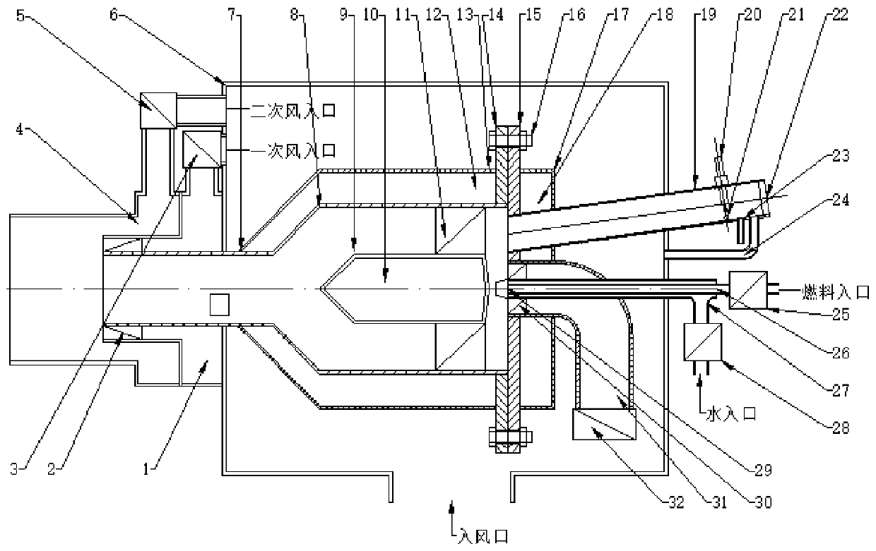
[0024] Specific implementation mode one: as figure 1 As shown, the binary horizontal burner of this embodiment includes a primary air supply chamber 1, a primary air distribution door 3, a secondary air supply chamber 4, a secondary air distribution door 5, a bellows 6, a mouth section 7, a cavity 8, Shock-absorbing heat collector 9, heat-resistant body 10, cavity flange 14, gland flange 15, gland insulation layer guard plate 17, ignition observation tube 19, observation mirror 22, ignition fluid input pipe 23, oxygen supply Pipe 24, fuel pipe 26, water supply pipe 27, mixing nozzle 29, main air duct 31, multiple first wind guide plates 2, multiple wind guide plates 30 and multiple fuel guide plates 11; the main structure of the burner is arranged on the air box 6, the cavity flange 14 and the inlet end of the cavity 8 are fixed as a whole, and the outlet end of the cavity 8 is coaxially connected with the cavity section 7, and the free end of the cavity section 7 is passed th...

specific Embodiment approach 2

[0028] Specific implementation mode two: as figure 1 As shown, in this embodiment, a plurality of fuel guide plates 11 are evenly distributed along the circumferential direction of the damping heat collector 9 . Such a design makes the fuel and water fully mixed and evenly mixed with air for combustion and cracking, and the angle of the guide plate determines the speed of its outlet. Other components and connections are the same as those in the first embodiment.

specific Embodiment approach 3

[0029] Specific implementation mode three: as figure 1 As shown, the air outlet of the main air duct 31 in this embodiment is uniformly provided with a plurality of air guide plates 30 along its circumferential direction. Such a design makes the air entering the main air duct 31 form a swirl wind, agitating the mixture of fuel and water into the cavity 8 evenly. Other compositions and connections are the same as those in Embodiment 1 or 2.


PUM


Abstract

The invention discloses a binary horizontal burner, and relates to a burner. According to the binary horizontal burner, the problems that an existing atomizing burner is high in energy consumption andpollute the environment, and an existing gasification burner easily generates carbon deposit are solved. A damping heat collector is arranged at the center of a cavity through a fuel guide plate, a gland flange is detachably connected to a cavity flange, an ignition observation tube is obliquely arranged, one end of the ignition observation tube communicates with the gland flange, the other end of the ignition observation tube is provided with an observation mirror, an ignition liquid input tube communicates with the ignition observation tube, one end of an oxygen delivery tube communicates with the ignition observation tube, the other end of the oxygen delivery tube communicates with an air box, an ignition needle and an ignition pool plate are arranged in the ignition observation tube,one end of a fuel tube is connected with the gland flange, one end of the fuel tube is provided with a mixing nozzle, the other end of the fuel tube is connected with a water supply tube, and one endof a main air tube is provided with air guide plates in the circumferential direction of the main air tube. The binary horizontal burner is used for a boiler, a hot blast heater and a drying furnace.

Description

technical field [0001] The invention relates to a burner, in particular to a binary horizontal burner. Background technique [0002] The burner is divided into atomization burner and gasification burner according to the fuel combustion method. The fuel of the atomization burner is liquid fuel and gas fuel, and the fuel of the gasification burner is liquid fuel. The existing atomization burner passes The mixed combustion of high-pressure atomized fuel and air, part of which is not atomized is blown out by high-speed wind, and the other part of combustible CO and other combustibles produced during combustion are blown away by high-speed wind, and more than 20% of the fuel that cannot be completely combusted is about 20%. High consumption; due to the low efficiency of combustion, the exhaust gas will pollute the surrounding environment; [0003] The existing gasification burner is divided into two types, one is an external evaporation and gasification device, which makes the f...

Claims


Application Information

Patent Timeline
Patent Type & Authority Applications(China)
IPC IPC(8): F23D11/38F23D11/40F23L9/00
CPCF23D11/38F23D11/40F23L9/00
Inventor 王振琦杨延中
Owner 王振琦
Why Eureka
Try Eureka