A hardware pipe cutting device

A cutting device and hardware technology, applied in the direction of pipe shearing device, shearing device, accessory device of shearing machine, etc., can solve the problems of hand affecting cutting efficiency, trouble, and high labor cost

Inactive Publication Date: 2020-07-24
浙江年代建设工程有限公司
View PDF5 Cites 0 Cited by
  • Summary
  • Abstract
  • Description
  • Claims
  • Application Information

AI Technical Summary

Problems solved by technology

[0002] In many building constructions, it is often necessary to use a large amount of materials, and metal pipes are one of them. However, metal pipes are initially very long, and they need to be cut to the required length before use. Usually people are Cutting the metal tube with a cutting tool in hand, because the hand needs to hold the cutting tool all the time, the hand is prone to soreness and affects the cutting efficiency after a long time, and people need to measure the cutting length of the metal tube before cutting, which is troublesome, so it is necessary Many people alternately cut the metal tube, and a group of people are required to mark the cut length of the metal tube, so the labor cost is high

Method used


Image

  • A hardware pipe cutting device
  • A hardware pipe cutting device
  • A hardware pipe cutting device

Examples


Embodiment 1

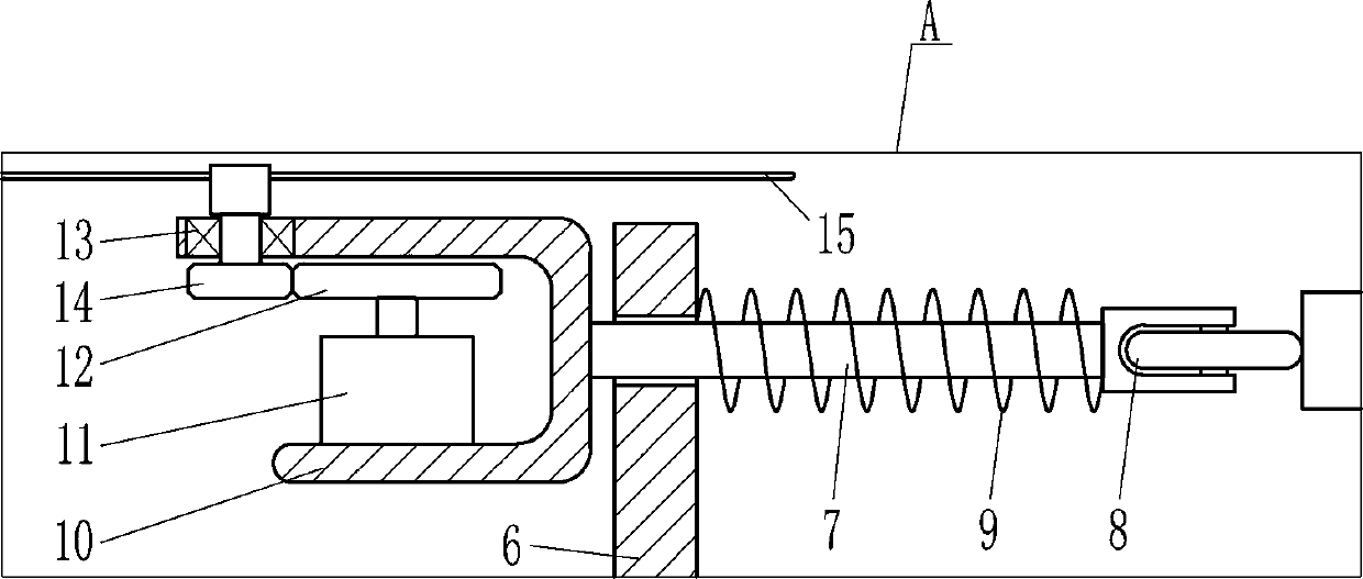
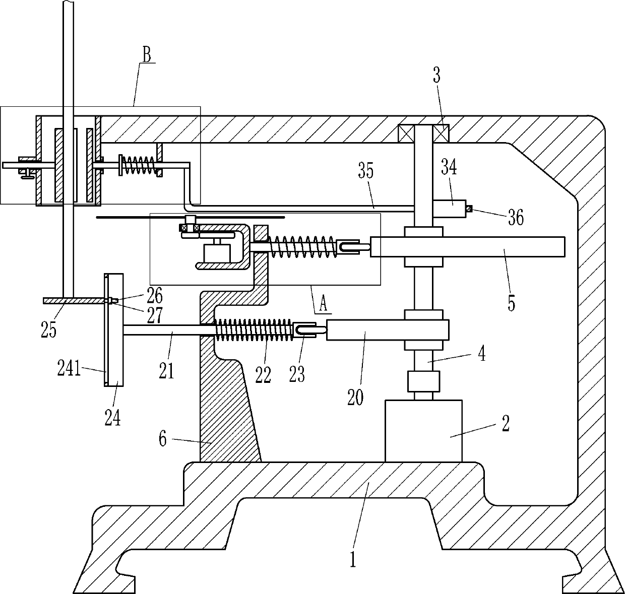
[0017] A hardware pipe cutting device, such as Figure 1-4 As shown, it includes a frame 1, a first motor 2, a first bearing 3, a shaft rod 4, a first cam 5, a first bracket 6, a first slide bar 7, a first roller seat 8, a first spring 9, Second bracket 10, second motor 11, spur gear 12, second bearing 13, shaft gear 14, cutting disc 15, frame 16, first guide sleeve 17, first guide rod 18 and adjustment device 19, inside frame 1 The first motor 2 is provided on the right side of the bottom, and the first bearing 3 is embedded in the top right side of the frame 1. The first bearing 3 is connected with a shaft 4, and the bottom end of the shaft 4 is connected to the first motor through a coupling. The output shaft of 2 is connected, the first cam 5 is provided in the middle of the shaft rod 4, the first bracket 6 is provided on the left side of the inner bottom of the frame 1, the frame 1 is connected with the first bracket 6 by welding, and the first bracket 6 The upper part i...

Embodiment 2

[0019] A hardware pipe cutting device, such as Figure 1-4 As shown, it includes a frame 1, a first motor 2, a first bearing 3, a shaft rod 4, a first cam 5, a first bracket 6, a first slide bar 7, a first roller seat 8, a first spring 9, Second bracket 10, second motor 11, spur gear 12, second bearing 13, shaft gear 14, cutting disc 15, frame 16, first guide sleeve 17, first guide rod 18 and adjustment device 19, inside frame 1 The first motor 2 is provided on the right side of the bottom, and the first bearing 3 is embedded in the top right side of the frame 1. The first bearing 3 is connected with a shaft 4, and the bottom end of the shaft 4 is connected to the first motor through a coupling. The output shaft of 2 is connected, the first cam 5 is provided in the middle of the shaft rod 4, the first bracket 6 is provided on the left side of the inner bottom of the frame 1, and the first sliding rod 7 is provided slidingly on the upper part of the first bracket 6, and the fir...

Embodiment 3

[0022] A hardware pipe cutting device, such as Figure 1-4As shown, it includes a frame 1, a first motor 2, a first bearing 3, a shaft rod 4, a first cam 5, a first bracket 6, a first slide bar 7, a first roller seat 8, a first spring 9, Second bracket 10, second motor 11, spur gear 12, second bearing 13, shaft gear 14, cutting disc 15, frame 16, first guide sleeve 17, first guide rod 18 and adjustment device 19, inside frame 1 The first motor 2 is provided on the right side of the bottom, and the first bearing 3 is embedded in the top right side of the frame 1. The first bearing 3 is connected with a shaft 4, and the bottom end of the shaft 4 is connected to the first motor through a coupling. The output shaft of 2 is connected, the first cam 5 is provided in the middle of the shaft rod 4, the first bracket 6 is provided on the left side of the inner bottom of the frame 1, and the first sliding rod 7 is provided slidingly on the upper part of the first bracket 6, and the firs...


PUM


Abstract

The invention relates to a cutting device, in particular to a hardware pipe cutting device. The purpose of the invention is to provide the hardware pipe cutting device through which manual work can bereplaced for cutting hardware pipes, the situation that the cutting efficiency is affected by hand ache is avoided, and the cut lengths of the hardware pipes can be consistent. According to the technical scheme, the hardware pipe cutting device comprises a rack, a first motor, a first bearing, a shaft rod, a first cam, a first support, a first sliding rod and the like, wherein the first motor isarranged on the right side of the bottom in the rack, and the first bearing is embedded in the right side of the top in the rack. A hardware pipe is moved to a position between clamping plates on thefront side and the rear side, the cutting position is moved to the right left side of a cutting blade, and the first motor and the second motor are started, and therefore the cutting blade can move leftwards to cut the hardware pipe, a person does not need to hold a cutting tool to cut the hardware pipe, the situation that the cutting efficiency is affected by hand ache is avoided, and the lengthof the hardware pipe cut each time can be consistent through the effect of a supporting plate.

Description

technical field [0001] The invention relates to a cutting device, in particular to a hardware pipe cutting device. Background technique [0002] In many building constructions, it is often necessary to use a large amount of materials, and metal pipes are one of them. However, metal pipes are initially very long, and they need to be cut to the required length before use. Usually people are Cutting the metal pipe with the cutting tool in hand, because the hand needs to hold the cutting tool all the time, the hand is easy to be sore and affect the cutting efficiency after a long time, and the person needs to measure the cutting length of the metal pipe before cutting, which is troublesome, so it is necessary Many people alternately cut the metal tube, and a group of people are required to mark the cut length of the metal tube, so the labor cost is high. Contents of the invention [0003] In order to overcome the disadvantages that the hand needs to hold the cutting tool all ...

Claims


Application Information

Patent Timeline
Patent Type & Authority Patents(China)
IPC IPC(8): B23D21/00B23D33/02
CPCB23D21/00B23D33/02
Inventor 王绍垒
Owner 浙江年代建设工程有限公司
Why Eureka
Try Eureka