Garden turf shaving device

A technology of turf removal, applied in botany equipment and methods, horticulture, lawn growth, etc., can solve problems such as troublesome, high labor costs, and high labor intensity

Active Publication Date: 2019-01-15
温州宇岚科技有限公司
View PDF7 Cites 1 Cited by
  • Summary
  • Abstract
  • Description
  • Claims
  • Application Information

AI Technical Summary

Problems solved by technology

[0002] In the garden, in order to make the environment better, people will lay a lot of turf, but after a long time, the turf will wither and turn yellow, so it needs to be removed and replaced with a new turf, usually people use a hoe To remove the turf, due to the large area of ​​the turf, it is necessary to continuously swing the hammer, which is labor-intensive, and a large amount of dust is likely to appear when the hoe contacts the land, which affects the surrounding environment and people, so people will sprinkle water before removing the turf, and often Three staff members work together to remove the turf, which is troublesome and labor-intensive

Method used


Image

  • Garden turf shaving device
  • Garden turf shaving device
  • Garden turf shaving device

Examples


Embodiment 1

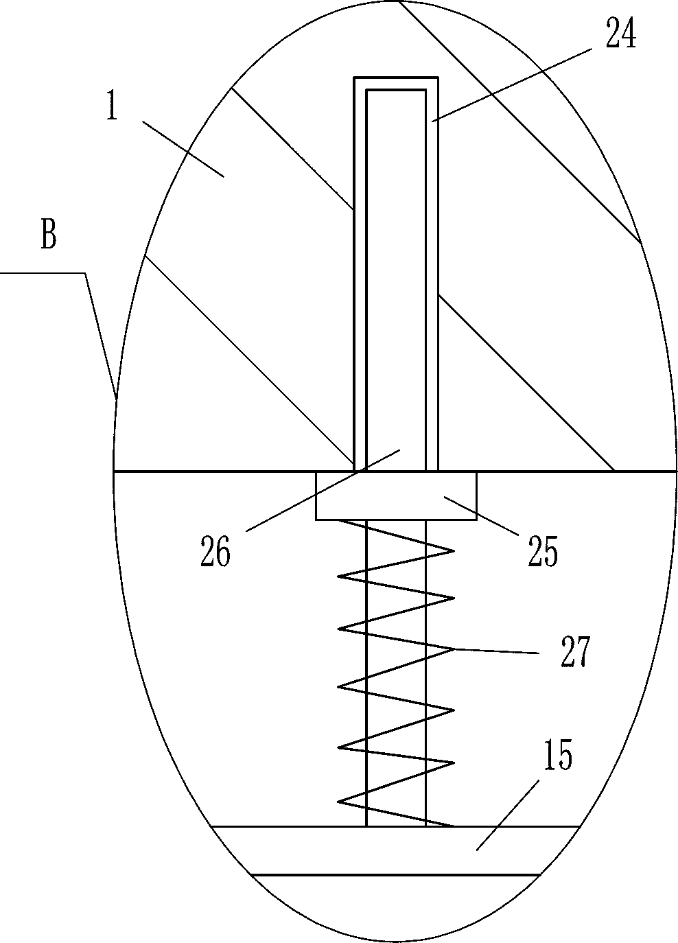
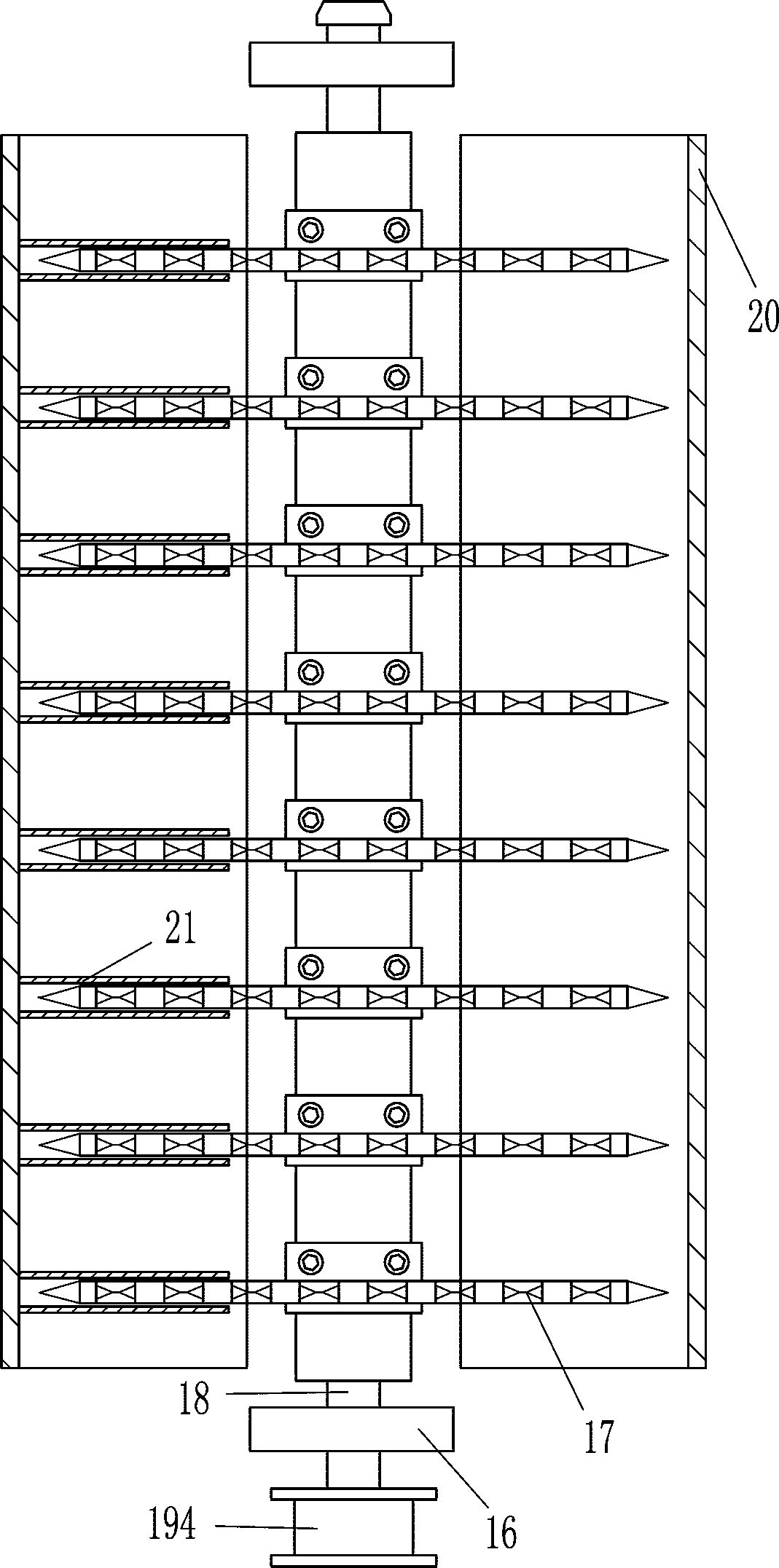
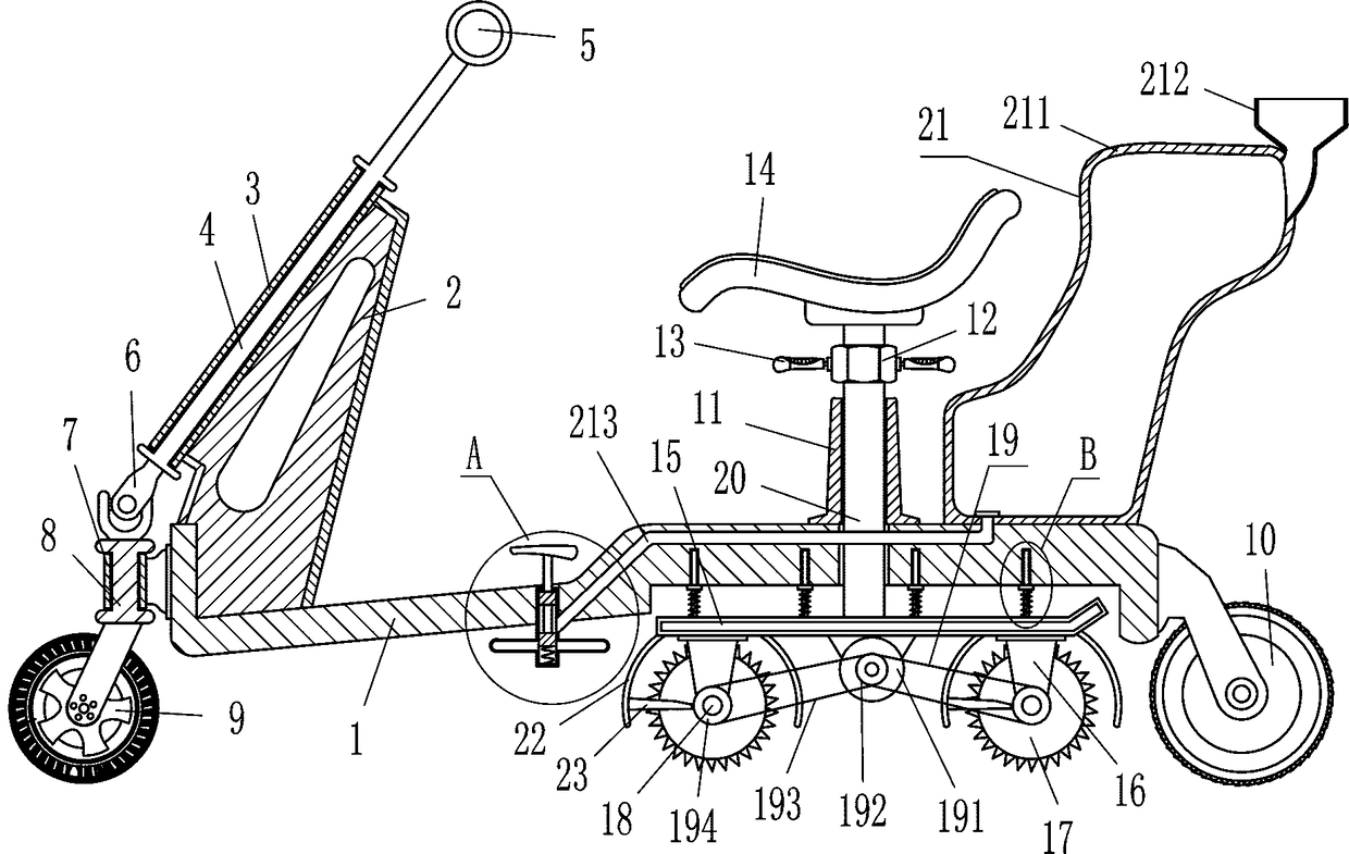
[0022] A garden turf removal equipment, such as Figure 1-4As shown, it includes a base 1, a support plate 2, a first shaft sleeve 3, a first rotating shaft 4, a fixed rod 5, a universal joint 6, a second shaft sleeve 7, a second rotating shaft 8, a driven wheel 9, and an electric roller 10 , the third shaft sleeve 11, the nut 12, the handle bar 13, the seat plate 14, the horizontal plate 15, the mounting plate 16, the planer wheel 17, the third rotating shaft 18, the driving device 19 and the vertical bar 20, and the top of the base 1 is fixedly connected with a Install the support plate 2 of the first shaft sleeve 3, the first shaft sleeve 3 is fixedly connected to the upper part of the left side of the support plate 2, the first shaft sleeve 3 is inclined, and the first shaft sleeve 3 is provided with the first rotating shaft 4, the first shaft sleeve 3 A fixed rod 5 is installed on the top of a rotating shaft 4, a second shaft sleeve 7 is fixedly connected to the middle pa...

Embodiment 2

[0024] A garden turf removal equipment, such as Figure 1-4 As shown, it includes a base 1, a support plate 2, a first shaft sleeve 3, a first rotating shaft 4, a fixed rod 5, a universal joint 6, a second shaft sleeve 7, a second rotating shaft 8, a driven wheel 9, and an electric roller 10 , the third shaft sleeve 11, the nut 12, the handle bar 13, the seat plate 14, the horizontal plate 15, the mounting plate 16, the planer wheel 17, the third rotating shaft 18, the driving device 19 and the vertical bar 20, and the top of the base 1 is fixedly connected with a Install the support plate 2 of the first shaft sleeve 3, the first shaft sleeve 3 is fixedly connected to the upper part of the left side of the support plate 2, the first shaft sleeve 3 is inclined, and the first shaft sleeve 3 is provided with the first rotating shaft 4, the first shaft sleeve 3 A fixed rod 5 is installed on the top of a rotating shaft 4, a second shaft sleeve 7 is fixedly connected to the middle p...

Embodiment 3

[0027] A garden turf removal equipment, such as Figure 1-4 As shown, it includes a base 1, a support plate 2, a first shaft sleeve 3, a first rotating shaft 4, a fixed rod 5, a universal joint 6, a second shaft sleeve 7, a second rotating shaft 8, a driven wheel 9, and an electric roller 10 , the third shaft sleeve 11, the nut 12, the handle bar 13, the seat plate 14, the horizontal plate 15, the mounting plate 16, the planer wheel 17, the third rotating shaft 18, the driving device 19 and the vertical bar 20, and the top of the base 1 is fixedly connected with a Install the support plate 2 of the first shaft sleeve 3, the first shaft sleeve 3 is fixedly connected to the upper part of the left side of the support plate 2, the first shaft sleeve 3 is inclined, and the first shaft sleeve 3 is provided with the first rotating shaft 4, the first shaft sleeve 3 A fixed rod 5 is installed on the top of a rotating shaft 4, a second shaft sleeve 7 is fixedly connected to the middle p...


PUM


Abstract

The invention relates to a shaving device and particularly relates to a garden turf shaving device. Therefore, the technical problem of the present invention is to provide a garden turf shaving devicecapable of cutting a turf into pieces, the removal of the turf by people is facilitated, the labor intensity is small, and water can be sprayed to reduce dust and avoid the influence on a surroundingenvironment. The technical solution of the invention is that the garden turf shaving device comprises a base, a support plate, a first shaft sleeve, a first rotating shaft, a fixed rod, a universal joint, a second shaft sleeve, a second rotating shaft, a driven wheel, an electric roller and a third shaft sleeve, the top of the base is fixedly connected to the support plate capable of installing the first shaft sleeve, the first shaft sleeve is fixedly connected to the upper part of a left side face of the support plate, and the first shaft sleeve is inclined. According to the shaving device,planing wheels are driven to rotate by starting a driving motor, the planing wheels are rotated to cut the turf, the planing wheels cut the turf into pieces through the electric roller, so the removalof the turf by people is facilitated, continuously waving a hoe is not needed, and time and labor are saved.

Description

technical field [0001] The invention relates to a cutting device, in particular to a garden turf cutting device. Background technique [0002] In the garden, in order to make the environment better, people will lay a lot of turf, but after a long time, the turf will wither and turn yellow, so it needs to be removed and replaced with a new turf, usually people use a hoe To remove the turf, due to the large area of ​​the turf, it is necessary to continuously swing the hammer, which is labor-intensive, and a large amount of dust is likely to appear when the hoe contacts the land, which affects the surrounding environment and people, so people will sprinkle water before removing the turf, and often It requires three staff members to plan the turf together, which is troublesome and the labor cost is high. Contents of the invention [0003] In order to overcome the disadvantages of constantly swinging the hammer due to the large area of ​​turf, the labor intensity is high, and ...

Claims


Application Information

Patent Timeline
Patent Type & Authority Applications(China)
IPC IPC(8): A01G20/10
CPCA01G20/10
Inventor 彭友江
Owner 温州宇岚科技有限公司
Why Eureka
Try Eureka