A super-clean high-efficiency vacuum cleaner
A vacuum cleaner, ultra-clean technology, applied in the direction of vacuum cleaners, suction filters, suction nozzles, etc., can solve the problems of poor dust removal effect and limited suction of vacuum cleaners, and achieve good dust removal effect
- Summary
- Abstract
- Description
- Claims
- Application Information
AI Technical Summary
Problems solved by technology
Method used
Image

Examples
Embodiment 1
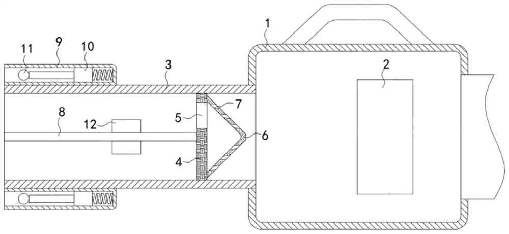
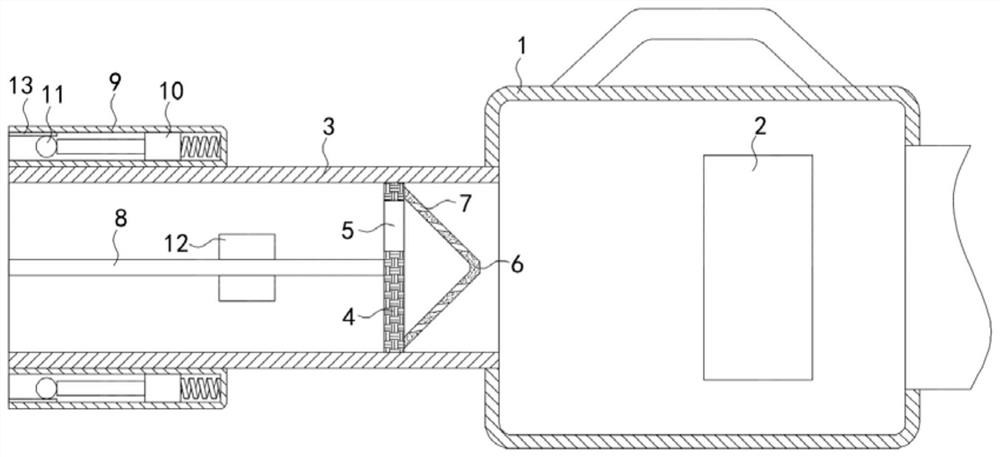
[0023] Such as Figure 1-2 As shown, an ultra-clean and high-efficiency vacuum cleaner includes a housing 1, and a fan 2 is arranged inside the housing 1. The air inlet of the fan 2 is connected to the suction pipe 3 at the front end of the housing 1, and the inner wall of the suction pipe 3 is sealed and rotated. Connected with a rotating plate 4, the rotating plate 4 is provided with a semicircular ventilation hole 5, the side wall of the rotating plate 4 is fixedly connected with a conical rotor 6, and the side wall of the conical rotor 6 is provided with a plurality of circumferential Arranged air channels 7, if the ports of each air channel 7 in the conical rotor 6 point to the vectors formed by the ports of each air channel 7 outside the conical rotor 6 as exhaust vectors, then the vectors of each air channel 7 The exhaust vector has an equal axial component pointing to the rear of the conical rotor 6, and a circumferential component that is rotationally symmetrical abou...
Embodiment 2
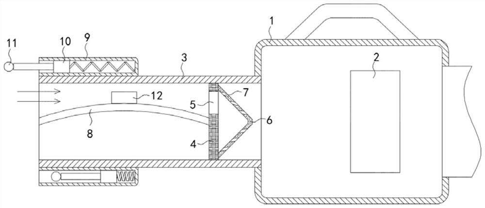
[0028] Such as image 3 As shown, the difference between this embodiment and Embodiment 1 is that the batting ball 11 is made of rubber material, and the inner wall of the pipe body 9 near the port is fixedly connected with a friction plate 13, and the side wall of the friction plate 13 is glued Attached fur.
[0029] In this embodiment, when the batting ball 11 moves back and forth in the tube body 9, it rubs against the friction plate 13. Because the rubber is rubbed by the fur, the rubber is negatively charged, and the batting ball 11 carries a negative charge to attract dust. And contact with the dust to make the dust negatively charged, further improving its dust removal effect.
Embodiment 3
[0031] Such as Figure 4-5 As shown, the difference between this embodiment and Embodiment 2 is that: the inner wall of the housing 1 is fixedly connected with a fixed ring 14, the inner wall of the fixed ring 14 is provided with silk cloth, and the inner wall of the fixed ring 14 rotates A rotating ring 15 is connected, and the rotating ring 15 is made of glass material. The inner wall of the rotating ring 15 is fixedly connected with a filter screen plate 16, and an impeller 17 is fixedly embedded in the filter screen plate 16.
[0032] In this embodiment, the airflow with dust passes through the filter screen plate 16, and the impeller 17 drives the filter screen plate 16 and the rotating ring 15 to rotate, and then the rotating ring 15 and the fixed ring 14 undergo rotational friction, and the glass and the silk friction produce friction. With a positive charge, the rotating ring 15 has a positive charge, and the filter screen plate 16 in contact with the rotating ring 15 ...
PUM
 Abstract
Description
Claims
Application Information
 - R&D
- Intellectual Property
- Life Sciences
- Materials
- Tech Scout
- Unparalleled Data Quality
- Higher Quality Content
- 60% Fewer Hallucinations
Browse by: Latest US Patents, China's latest patents, Technical Efficacy Thesaurus, Application Domain, Technology Topic, Popular Technical Reports.
© 2025 PatSnap. All rights reserved.Legal|Privacy policy|Modern Slavery Act Transparency Statement|Sitemap|About US| Contact US: help@patsnap.com