
Dust removing and falling device for construction sites

A dust suppression device and construction site technology, which is applied in construction, combined devices, cleaning methods and appliances, etc., can solve the problems of high cost and insufficient environmental protection, and achieve the effects of simple structure, increased dust absorption area, and strong practicability

Inactive Publication Date: 2018-05-04
ZHENGZHOU CHENGHE INFORMATION TECH CO LTD
View PDF8 Cites 25 Cited by
  • Summary
  • Abstract
  • Description
  • Claims
  • Application Information

AI Technical Summary

Problems solved by technology

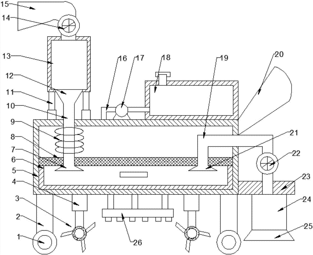
[0002] Architecture is the general term for buildings and structures. It is an artificial environment created by people using material and technical means and certain scientific laws, Feng Shui concepts and aesthetic principles to meet the needs of social life. Dust removal devices are commonly known as dust collectors. Or a device that reduces the content of fly ash in the flue gas; the types of dust removal devices can be divided into bionano film dust suppression devices, cloud and fog dust suppression devices, cloud and fog dust suppression devices, bag dust removal devices, cyclone dust removal devices, wet dust removal devices, and electrostatic dust removal devices , Desulfurization and dust removal device; used in chemical industry, petroleum, metallurgy, construction, mining, machinery, textile and other industries, the existing dust suction and dust removal device has the disadvantages of not being environmentally friendly and high cost, so it is necessary to develop an environmentally friendly, low-cost, Dust removal and dust reduction device for construction sites with thorough dust removal and dust suction

Method used


Image

  • Dust removing and falling device for construction sites
  • Dust removing and falling device for construction sites
  • Dust removing and falling device for construction sites

Examples


Embodiment Construction

[0016] The technical solution of this patent will be further described in detail below in conjunction with specific embodiments.

[0017] Embodiments of the present patent are described in detail below, examples of which are shown in the drawings, wherein the same or similar reference numerals designate the same or similar elements or elements having the same or similar functions throughout. The embodiments described below by referring to the figures are exemplary and are only used for explaining the patent, and should not be construed as limiting the patent.

[0018] In the description of this patent, it is to be understood that the terms "center", "upper", "lower", "front", "rear", "left", "right", "vertical", "horizontal", The orientation or positional relationship indicated by "top", "bottom", "inner", "outer", etc. is based on the orientation or positional relationship shown in the drawings, and is only for the convenience of describing this patent and simplifying the des...


PUM


Abstract

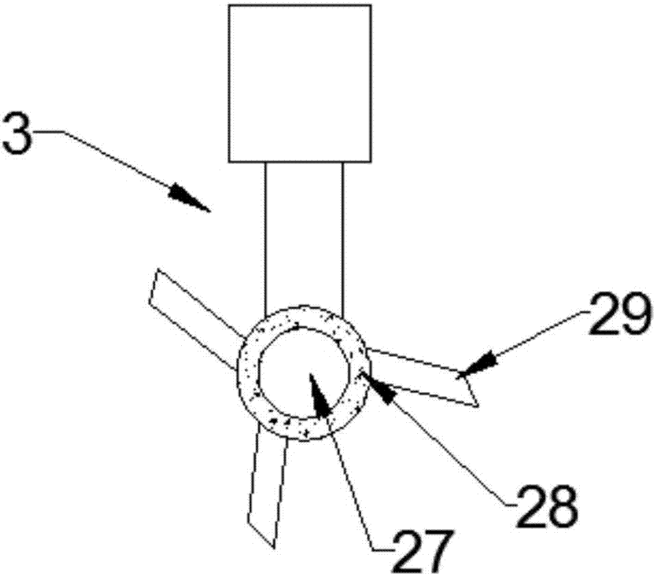
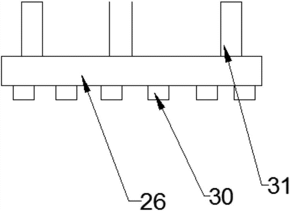
The invention provides a dust removing and falling device for construction sites, and belongs to the technical field of construction dust removal. The dust removing and falling device comprises a dustremoving and collecting device, and a water spraying and dust falling device; a feed cylinder is fixedly arranged at the upper end of a hydraulic extension rod; a spring extension pipe is arranged ona connecting pipe; a collecting container is arranged at the bottom of an inner cavity of a collecting box; a cleaning device is arranged below the extension rod; a dust sucking cylinder is arrangedat the lower end of a fixed plate; the lower side of the left side of a water tank is connected with a water pump through a water outlet pipe; and the left end of the water pump is connected with a water spraying plate through a water outlet pipe. As the feed cylinder is fixedly arranged at the upper end of the hydraulic extension rod, the device achieves a function of conveniently adjusting the height of the feed cylinder to conveniently remove dust in the construction sites; the water spraying plate is arranged below the collecting box through a support rod to achieve functions of water spraying and dust falling; and the device has the characteristics of simple structure, high practicability and good dust removing and falling effects.

Description

technical field [0001] The invention relates to a building-related facility, in particular to a dust removal and dust reduction device for a construction site. Background technique [0002] Architecture is the general term for buildings and structures. It is an artificial environment created by people using material and technical means and certain scientific laws, Feng Shui concepts and aesthetic principles to meet the needs of social life. Dust removal devices are commonly known as dust collectors. Or a device that reduces the content of fly ash in the flue gas; the types of dust removal devices can be divided into bionano film dust suppression devices, cloud and fog dust suppression devices, cloud and fog dust suppression devices, bag dust removal devices, cyclone dust removal devices, wet dust removal devices, and electrostatic dust removal devices , Desulfurization and dust removal device; used in chemical industry, petroleum, metallurgy, construction, mining, machinery,...

Claims


Application Information

Patent Timeline
Patent Type & Authority Applications(China)
IPC IPC(8): B08B5/04E01H1/05E01H1/08E01H3/02B01D50/00
CPCE01H1/056E01H1/0827E01H1/0854E01H3/02B08B5/04B01D50/60
Inventor 张强
Owner ZHENGZHOU CHENGHE INFORMATION TECH CO LTD
Learn More