
Ceramic dielectric filter and method for conducting and fixing ceramic dielectric filter and antenna coupling plate

A ceramic dielectric, antenna coupling technology, applied in antenna coupling, antenna, waveguide type devices and other directions, can solve the problems of contact instability, waste, antenna coupling plate damage, etc., to solve the problem of inconvenient disassembly and assembly, stable signal transmission, and guaranteed stability sexual effect

Inactive Publication Date: 2019-11-29
TONGYU COMM INC
View PDF8 Cites 4 Cited by
  • Summary
  • Abstract
  • Description
  • Claims
  • Application Information

AI Technical Summary

Problems solved by technology

[0006] However, the conduction and fixing methods of the current ceramic dielectric filter and the antenna coupling plate still have many deficiencies. Usually, the filter and the antenna coupling plate are conducted through electrodes or pins inserted into the ceramic cavity, and the grounding solder joint Fix the filter on the antenna coupling board by surface mount (solder soldering)
The welded electrodes or pins are fixed on the filter as a whole. The assembly or use process is easily affected by stress, breakage or unstable contact, which will affect the signal transmission and the performance of the entire antenna. The fixed filter in the solder paste welding method, in the filter It is very inconvenient to disassemble and assemble when the antenna is defective or damaged, and it is easy to damage the antenna coupling plate, resulting in greater loss and waste

Method used


Image

  • Ceramic dielectric filter and method for conducting and fixing ceramic dielectric filter and antenna coupling plate
  • Ceramic dielectric filter and method for conducting and fixing ceramic dielectric filter and antenna coupling plate
  • Ceramic dielectric filter and method for conducting and fixing ceramic dielectric filter and antenna coupling plate

Examples


Embodiment Construction

[0030] The present invention will be described in further detail below in conjunction with the accompanying drawings and specific embodiments.

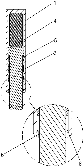
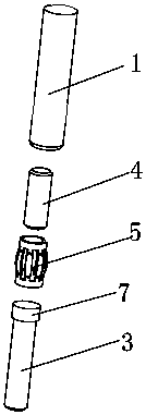
[0031] The present invention proposes a ceramic dielectric filter, which includes a pogo pin assembly arranged in a ceramic cavity, and the pogo pin assembly is used to realize the conduction connection between the ceramic dielectric filter and the antenna coupling plate, such as figure 1 As shown, the pogo needle assembly includes a needle tube 1, a spring 2 and a contact needle 3 arranged in the needle tube 1, the upper end of the needle tube 1 closes the lower end opening, and the spring 2 is located on the upper end surface of the contact needle 3 and the inner top surface of the needle tube 1 Between, the pogo pin assembly is inserted into the cavity of the filter and the needle tube 1 is welded by solder paste, and the contact pin 3 can slide in the needle tube 1 .

[0032] Further, the upper end of the contact pin 3 is provide...


PUM


Abstract

The invention relates to a ceramic dielectric filter and a method for conducting and fixing the ceramic dielectric filter and an antenna coupling plate. The filter adopts a spring pin assembly, wherein the spring pin assembly comprises a pin tube, a spring and a contact pin, the spring and the contact pin are arranged in the pin tube, the spring can buffer stress to prevent the contact pin from being damaged, and the stability of signal transmission between the contact pin and the antenna coupling can also be ensured. The ceramic dielectric filter is assembled and fixed by means of crimping ashielding fixing cover, so that the defects of easy damage or unstable contact of the ceramic dielectric filter in the prior art due to the adoption of electrode or contact pin welding for signal transmission and inconvenient disassembly caused by welding and fixing the filter are overcome, the signal transmission performance of the ceramic dielectric filter is improved, the signal transmission isstable, and the disassembly is convenient.

Description

technical field [0001] The invention relates to the technical field of communication filtering, in particular to a ceramic dielectric filter and a conduction and fixing method with an antenna coupling plate. Background technique [0002] 5G large-scale antenna system architecture, including dense radiation array, power division network, coupling calibration network, blind mating connector and transceiver unit. The dense radiation array is composed of several dual-polarized radiation units according to a certain horizontal and vertical spacing; in order to reduce the mutual coupling effect of the dense array, the direction of each radio frequency channel is improved. Figure 1 Consistency and port isolation, decoupling devices are designed in the dense radiation array; the power division network excites and configures the amplitude and phase of a group of radiation units contained in each unit module, and the number of radiation units excited by each power division network 1....

Claims


Application Information

Patent Timeline
Patent Type & Authority Applications(China)
IPC IPC(8): H01P1/20H01P1/207H01Q3/26H01Q1/52H01Q19/10H01R13/02H01R4/48H01R4/60
CPCH01P1/2002H01P1/207H01Q1/526H01Q3/267H01Q19/104H01R4/48H01R4/4809H01R4/4863H01R4/60H01R13/02
Inventor 成钢黄锦军彭蛟吴运松方敏杰陈志军
Owner TONGYU COMM INC
Learn More