
Material increase and material decrease comprehensive manufacturing method of hard alloy part with complex shape

A technology of cemented carbide and complex shapes, which is applied in the direction of additive processing, metal processing equipment, transportation and packaging, etc. It can solve the problems of difficult forming and poor surface quality, and achieve low strength of the green body, easy machining, and elimination of The effect of the step effect

Inactive Publication Date: 2019-11-29
DONGHUA UNIV
View PDF8 Cites 1 Cited by
  • Summary
  • Abstract
  • Description
  • Claims
  • Application Information

AI Technical Summary

Problems solved by technology

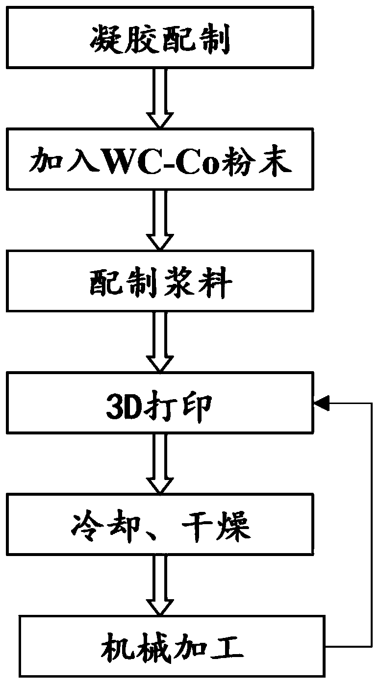
[0006] The technical problem to be solved by the present invention is to provide a comprehensive additive-subtractive manufacturing method for cemented carbide parts with complex shapes, which overcomes the defects of difficult forming of complex shapes and poor surface quality of cemented carbide green parts in the prior art. The invented moldless manufacturing method for the manufacture of complex cemented carbide parts, which belongs to a composite manufacturing technology that combines additive manufacturing and mechanical cutting of parts

Method used


Image

  • Material increase and material decrease comprehensive manufacturing method of hard alloy part with complex shape
  • Material increase and material decrease comprehensive manufacturing method of hard alloy part with complex shape
  • Material increase and material decrease comprehensive manufacturing method of hard alloy part with complex shape

Examples


Embodiment 1

[0035] Complicated shape WC-wt.8% Co cemented carbide parts:

[0036] 1) Preparation of gel system: Dissolve 9.3g of polystyrene-butadiene-styrene SBS (commercially available, model YH-792) in 90mL of toluene, and heat at 60°C to form a gel solution;

[0037] 2) Slurry preparation: Add 729 g of YG8 cemented carbide (commercially available, WC particle diameter 0.8 μm, Co particle diameter 0.5 μm, Co content wt.8%) powder in the above 1) gel solution, and use magnetic The agitator is stirred into a slurry, and the viscosity of the slurry is 350±20mPa·s;

[0038] 3) 3D printing NC programming: According to the requirements of the part drawings, use the 3D modeling software to model the parts and import them into the 3D printing device.

[0039] 4) 3D printing: transport the slurry in 2) to a 3D printing device, and perform 3D printing according to the control program in 3), with an extrusion speed of 20mm / s.

[0040] 5) Milling: When the 3D printed parts in 4) are accumulated ...

Embodiment 2

[0043] Complicated Shape WC-wt.6%Co Cemented Carbide Parts

[0044] 1) Preparation of the gel system: 18.6 g of polystyrene-butadiene-styrene (SBS) was dissolved in 90 mL of toluene, and heated at a constant temperature of 60 ° C to form a gel solution;

[0045] 2) Slurry preparation: Add 729 g of YG6 cemented carbide (commercially available, WC particle diameter 0.8 μm, Co particle diameter 0.5 μm, Co content wt.6%) powder in the above 1) gel solution, and use magnetic force The agitator is stirred into a slurry, and the viscosity of the slurry is 400±20mPa·s;

[0046] 3) 3D printing NC programming: According to the requirements of the part drawings, use the 3D modeling software to model the parts and import them into the 3D printing device.

[0047] 4) 3D printing: transport the slurry in 2) to a 3D printing device, and perform 3D printing according to the control program in 3), with an extrusion speed of 20mm / s.

[0048] 5) Milling processing: When the 3D printed parts in...


PUM

PropertyMeasurementUnit
particle sizeaaaaaaaaaa
viscosityaaaaaaaaaa
thicknessaaaaaaaaaa

Abstract

The invention relates to a material increase and material decrease comprehensive manufacturing method of a hard alloy part with the complex shape. The method comprises the steps that segmented copolymer is dissolved in organic solvent, and a reversible gelatin system is prepared; hard alloy powder is added into the gelatin system, and slurry is prepared; the slurry is conveyed to a 3D printing device, and a multi-layer green body layer is formed according to the design requirement of a drawing; and a green body layer with a certain thickness is formed, and machined mechanically after being cooled and cured. According to the method, the 3D printing technology is utilized for directly forming the part with the complex shape, a mould does not need to be customized, meanwhile, a mechanical machining method helps to carry out milling machining, the step effect in the 3D printing process is eliminated, and the manufacturing precision of the part is ensured.

Description

technical field [0001] The invention belongs to the field of forming, processing and preparation of metal parts, and in particular relates to a composite additive-subtractive manufacturing method for hard alloy parts with complex shapes. Background technique [0002] Cemented carbide has a series of advantages such as high strength, high hardness, and high wear resistance, and is widely used in cutting tools, molds, and wear-resistant parts. Electric machining and grinding are the main processing methods for forming cemented carbide parts at present, but it is difficult to manufacture large and complex shape parts. Gel injection molding is a method widely used in the molding of metal parts in the field of powder metallurgy. By mixing the metal powder mixture with the pre-prepared gel solution, a slurry with a certain viscosity is prepared. The slurry is injected into the mold to form the part body. Although the gel injection molding process has the advantages of preparing ...

Claims


Application Information

Patent Timeline
Patent Type & Authority Applications(China)
IPC IPC(8): B22F3/22B22F3/24B22F1/00C22C29/08B33Y10/00
CPCB22F3/227B22F3/24C22C29/08C22C29/067B33Y10/00B22F2003/247B22F1/10
Inventor 张建国原一高张金江阮钧
Owner DONGHUA UNIV
Learn More