Cabinet type air conditioner indoor unit
A cabinet-type air conditioner and indoor unit technology, which is applied to air-conditioning systems, heating methods, and air quality improvement. It can solve problems such as low working efficiency of the cabinet-type air conditioner indoor unit and unsatisfactory heat exchange effect of the evaporator, and improve user experience. , reduce volatility, and shorten the stroke
- Summary
- Abstract
- Description
- Claims
- Application Information
AI Technical Summary
Problems solved by technology
Method used
Image

Examples
Embodiment 1
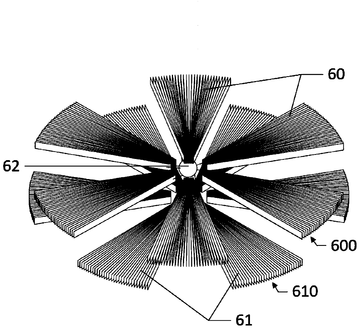
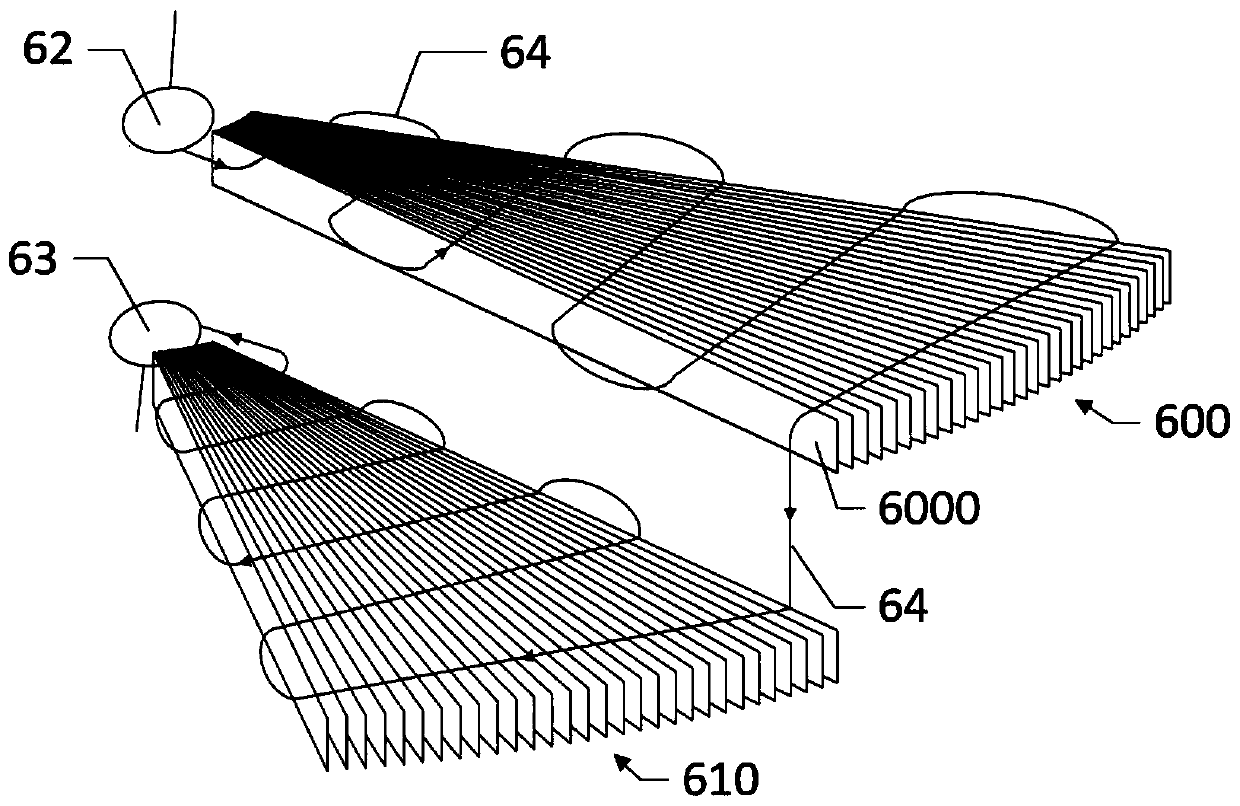
[0056] First refer to figure 1 with figure 2 , describe the evaporator provided by the present invention. in, figure 1 Schematic diagram of the structure of the evaporator provided in Embodiment 1 of the present invention; figure 2 It is a schematic diagram of the connection between two adjacent fin groups and sub-coils in the evaporator provided in Example 1 of the present invention.
[0057] Such as figure 1 with figure 2 As shown, the evaporator 6 used in the cabinet air conditioner indoor unit provided in this embodiment includes a coil tube, a first fin layer 60 and a second fin layer 61 . Such as figure 1 As shown in , the first fin layer 60 and the second fin layer 61 are spaced up and down, and are connected together by connecting members such as brackets, and the coil is connected to the first fin layer 60 and the second fin layer 61, Refer to the specific connection method figure 2 , figure 1 In order to show the structure of the fin layer, the coil is n...
Embodiment 2
[0066] refer to Figure 3-Figure 8 , image 3 A working diagram of the indoor unit of the cabinet air conditioner provided by Embodiment 2 of the present invention, which shows the air circulation path in operation; Figure 4 The working schematic diagram of the cabinet-type air conditioner indoor unit provided by Embodiment 2 of the present invention, which shows the air circulation path inside the cylindrical shell; Figure 5 A schematic cross-sectional view of the annular air outlet structure provided by Embodiment 2 of the present invention, which shows the situation in which the first air outlet is opened; Image 6 A schematic cross-sectional view of the annular air outlet structure provided by Embodiment 2 of the present invention, which shows the situation where the second air outlet is opened; Figure 7 The schematic cross-sectional structure diagram of the water receiving tray provided by Embodiment 2 of the present invention, which shows the first installation method...
Embodiment 3
[0073] refer to Figure 9-Figure 13 , Figure 9 A schematic diagram of the operation of the cabinet air conditioner indoor unit provided by Embodiment 3 of the present invention, which shows the air circulation path in operation; Figure 10 A schematic diagram of the operation of the indoor unit of the cabinet air conditioner provided by Embodiment 3 of the present invention, which shows the air circulation path inside the cylindrical shell; Figure 11 Schematic diagram of the structure of the sterilization and purification module provided in Example 3 of the present invention; Figure 12 for Figure 11 sectional schematic diagram of Figure 13 for Figure 11 top view.
[0074] The main structure of the cabinet type air conditioner indoor unit provided in this embodiment is basically the same as that of the cabinet type air conditioner indoor unit in Embodiment 2. The difference from the cabinet type air conditioner indoor unit in Embodiment 2 is that the cabinet type air...
PUM
 Abstract
Description
Claims
Application Information
 - R&D
- Intellectual Property
- Life Sciences
- Materials
- Tech Scout
- Unparalleled Data Quality
- Higher Quality Content
- 60% Fewer Hallucinations
Browse by: Latest US Patents, China's latest patents, Technical Efficacy Thesaurus, Application Domain, Technology Topic, Popular Technical Reports.
© 2025 PatSnap. All rights reserved.Legal|Privacy policy|Modern Slavery Act Transparency Statement|Sitemap|About US| Contact US: help@patsnap.com