
Air conditioner indoor unit

A technology for air-conditioning indoor units and fuselages, which is applied in air-conditioning systems, space heating and ventilation, space heating and ventilation details, etc., and can solve the problems that heat exchangers are difficult to exchange heat evenly with airflow, and the heat exchange effect is not ideal , to achieve the effect of enhancing self-healing ability, enhancing human immunity and promoting human metabolism

Pending Publication Date: 2019-11-22
QINGDAO HAIER AIR CONDITIONER GENERAL CORP LTD +1
View PDF9 Cites 0 Cited by
  • Summary
  • Abstract
  • Description
  • Claims
  • Application Information

AI Technical Summary

Problems solved by technology

[0005] In order to solve the above-mentioned problems in the prior art, that is, in order to solve the problem that the heat exchanger of the existing air conditioner is difficult to uniformly exchange heat with the air flow and the heat exchange effect is not ideal, the present invention provides an air-conditioning indoor unit. The machine includes a housing, a sterilization and purification module arranged in the housing, a water receiving tray, a heat exchanger and an air blower, the water receiving tray is arranged below the heat exchanger, and the housing is provided with The air inlet and the first air outlet, the heat exchanger includes a liquid separation member, a refrigerant output pipe, a coil and fins, the liquid separation member and the refrigerant output pipe are arranged up and down, and the coil includes a multi-section connection and the two ends of each section of the connecting pipe are respectively connected to the liquid separating member and the refrigerant output pipe, the fins are arranged on the multi-section connecting pipe, the shape of the refrigerant output pipe is non-linear, The multi-section connecting pipe is arranged to spread outward from the liquid separating member to the refrigerant output pipe

Method used


Image

  • Air conditioner indoor unit
  • Air conditioner indoor unit
  • Air conditioner indoor unit

Examples


Embodiment 1

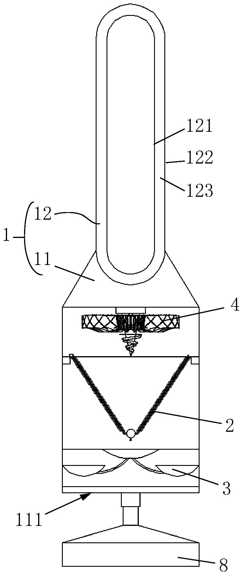
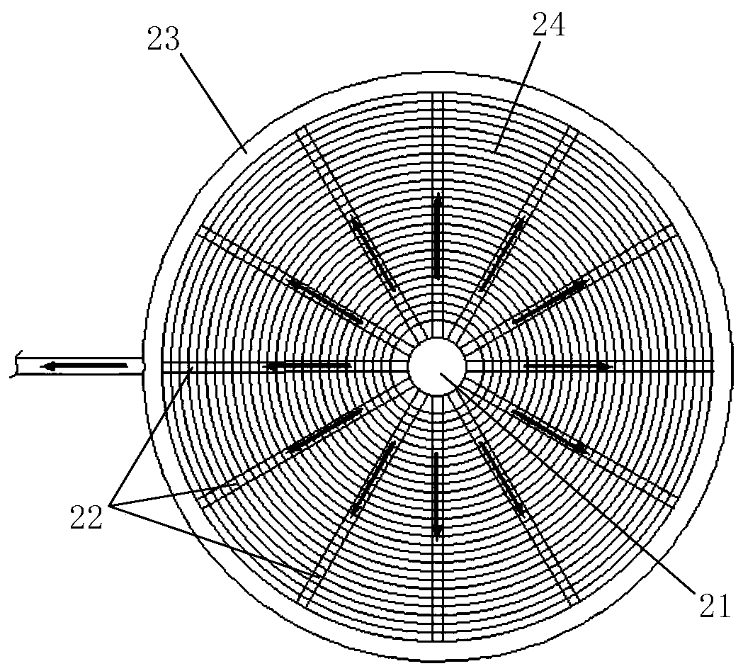
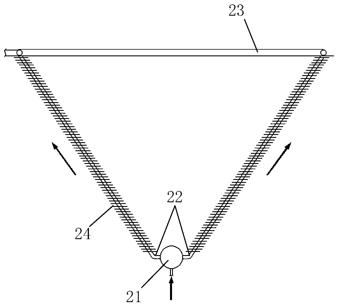
[0045] Embodiment 1: as figure 2 and image 3 ( image 3 As shown in the forward structural schematic view of the heat exchanger in vertical section), the heat exchanger 2 of the present invention includes a liquid separating member 21 , a refrigerant output pipe 23 , coils and fins 24 . Wherein, the liquid separating member 21 and the refrigerant output pipe 23 are arranged up and down. The liquid separating member 21 communicates with the refrigerant input pipeline of the air conditioner, and the refrigerant output pipe 23 communicates with the refrigerant output pipe 23 of the air conditioner. The coil tube includes a plurality of connecting pipes 22, and the two ends of each connecting pipe 22 are respectively connected to the liquid separating member 21 and the refrigerant output pipe 23, so as to form a plurality of refrigerant flow branches between the liquid separating member 21 and the refrigerant output pipe 23, Therefore, the plurality of refrigerants flowing in...

Embodiment 2

[0069] Embodiment 2: as Figure 8 As shown, the cabinet-type air conditioner indoor unit of the present invention is any one of the air conditioner indoor units described in Embodiment 1, and the heat exchanger 2 of the air conditioner indoor unit is any one of the heat exchangers 2 described in Embodiment 1. On this basis, the cabinet-type air conditioner indoor unit also includes a humidifying device 5, so that the cabinet-type air conditioner indoor unit of the present invention has a humidifying function, and can increase the humidity of the indoor air while adjusting the indoor temperature.

[0070] Preferably, the heat exchanger 2 of the cabinet-type air conditioner indoor unit is the funnel-shaped heat exchanger 2 in Embodiment 1. According to the flow path of the airflow, the above-mentioned water receiving tray 3, the above-mentioned funnel-shaped heat exchanger 2, the blower fan 4 and the humidifying device 5 are arranged in sequence. Among them, the structure of th...

Embodiment 3

[0075] Embodiment 3: as Figure 9 As shown, the cabinet-type air conditioner indoor unit of the present invention is any one of the air conditioner indoor units described in Embodiment 1, and the heat exchanger 2 of the air conditioner indoor unit is any one of the heat exchangers 2 described in Embodiment 1. On this basis, the cabinet-type air conditioner indoor unit also includes a sterilization and purification module 6 arranged in the casing 1 . Specifically, the above-mentioned sterilizing and purifying specifically refers to killing and filtering and purifying impurities such as bacteria and dust in the airflow, so as to reduce air pollutants such as bacteria and dust in the airflow ejected by the indoor unit of the cabinet air conditioner of the present invention. The carrying capacity enables the indoor unit of the cabinet air conditioner to improve the indoor air quality while adjusting the indoor temperature.

[0076]In a preferred embodiment, the heat exchanger 2 o...


PUM


Abstract

The invention belongs to the technical field of air conditioners, and particularly relates to an air conditioner indoor unit. A coil pipe of a heat exchanger is outwards diffused from a liquid distribution component to a refrigerant output pipe, so that multi-section connecting pipes of the coil pipe can form a larger frame structure together; heat exchange positions of the heat exchanger are spread and distributed, and heat exchange positions of the coil pipe are thereby dispersed in the air flow; and heat exchange uniformity of the heat exchanger and the air flow is increased. According to the diffusion frame structure, arrangement space of fins is increased, and heat exchange area is increased; namely, heat exchange performance of the heat exchanger is obviously improved by diffusion arrangement of the heat exchange positions and enlargement of the heat exchange area. In addition, a sterilization purification module is arranged at an air inlet of the air conditioner indoor unit, sothat indoor air can be effectively circulated, sterilized and purified during operation of the indoor unit; cleanliness of indoor air is improved; and air pollutants such as bacteria and dust in the air are reduced.

Description

technical field [0001] The invention belongs to the technical field of air conditioners, and in particular relates to an air conditioner indoor unit. Background technique [0002] As air conditioners are widely used in thousands of households, users have higher and higher requirements for the performance of air conditioners. Take the cabinet air conditioner as an example. Usually under the same conditions, the performance of the cabinet air conditioner depends on the heat exchange efficiency, and the heat exchange efficiency is directly related to the heat exchange area. The larger the heat exchange area, the higher the heat exchange efficiency. high. [0003] Usually, the structure and arrangement of the heat exchanger directly determine the size of the heat exchange area and the heat exchange efficiency. In existing cabinet-type air conditioners, the heat exchanger is usually placed obliquely in the air conditioner shell or attached to the air inlet. Usually, in order t...

Claims


Application Information

Patent Timeline
Patent Type & Authority Applications(China)
IPC IPC(8): F24F1/005F24F1/0014F24F1/0063F24F1/0067F24F1/0038F24F13/10F24F13/22
CPCF24F1/005F24F1/0014F24F1/0063F24F1/0067F24F1/0038F24F13/10F24F13/222
Inventor 刘光朋史为品曾福祥
Owner QINGDAO HAIER AIR CONDITIONER GENERAL CORP LTD
Learn More